WK4DS Amateur Radio Blog
Search Posts

POTA and understanding your nanoVNA
This means I have to make a little board up that will allow me to plug the coax into one side and connect it to the base of the antenna on the other. Since I use BNC connectors in the field, this should be pretty easy. I don’t want to let the cat out of the bag just yet, but what this really is, is a L network antenna tuner…
Today I was back over at my local park and while setting up the activation, I took note of the Smith Chart values for my tuned antenna on 20 meters. This took me down a rabbit hole and now I want to implement the changes to see how well it works.
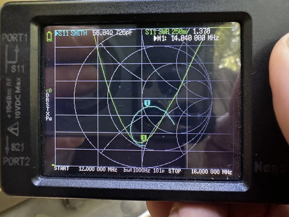
As you can see in the photo, I had the SWR plot on at the same time as the Smith Chart. When I am “on a clock” I will ignore the Smith Chart portion and just focus on the SWR plot. This is simple as all I have to do is place the radials in the usual position and then collapse or extend the antenna a little at a time to move the null over to where I want to operate. Is this antenna efficient? Not really. Does it get me on the air quickly and making contacts? Absolutely!
The information on the display above shows a lot of information. You can see with the SWR plot that the antenna is still just a touch too long. It is close enough to use, but if I wanted better bandwidth for CW use, I should shorten it a little more. You can also see where the same value is on the Smith chart at the same time. It is plotted below the resistive line, so it is capacitive. This is also confirmed at the top where you see 726pF. It is also above 50 ohms of impedance since it is inside the unity circle for 50 ohms, just a little bit.
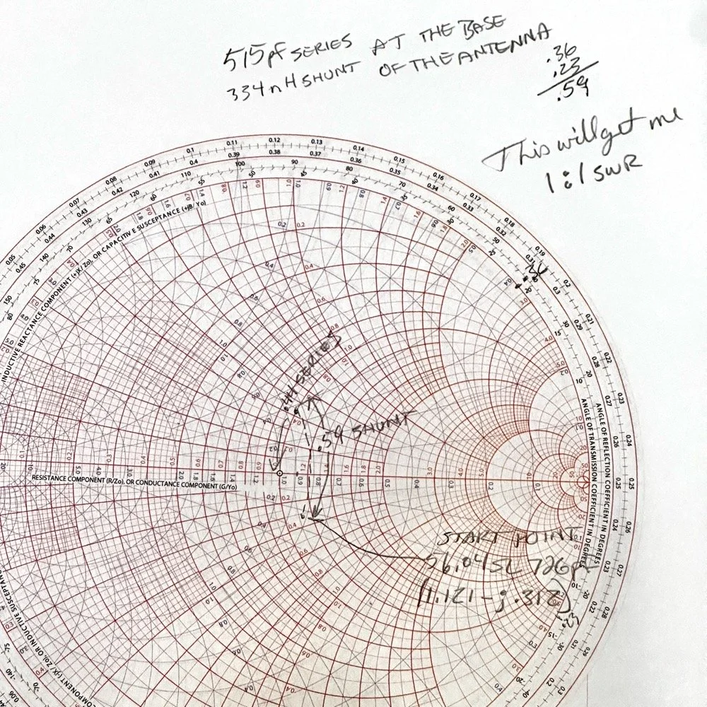
The Smith chart is really cool once you start understanding it a little. BTW…a little is all I really know about these powerful tools. It would seem to be counter productive to put an inductor from the antenna radiator to ground. It would also seem even more so with one of a very small inductance. But the Smith chart don’t lie… It looks like a hand wound air core inductor and a 550pF trimmer cap are the goodies here. or at least a 500pF cap and a 50pF trimmer to tune it with. The catch here is that the inductor shunts to ground BEFORE the capacitor is wired in series with the antenna. This is because my first “movement” on the chart is up (which indicates using inductance) and along the conductance lines (blue lines). THEN the capacitor is in series with the antenna after the inductor.
This means I have to make a little board up that will allow me to plug the coax into one side and connect it to the base of the antenna on the other. Since I use BNC connectors in the field, this should be pretty easy. I don’t want to let the cat out of the bag just yet, but what this really is, is a L network antenna tuner…
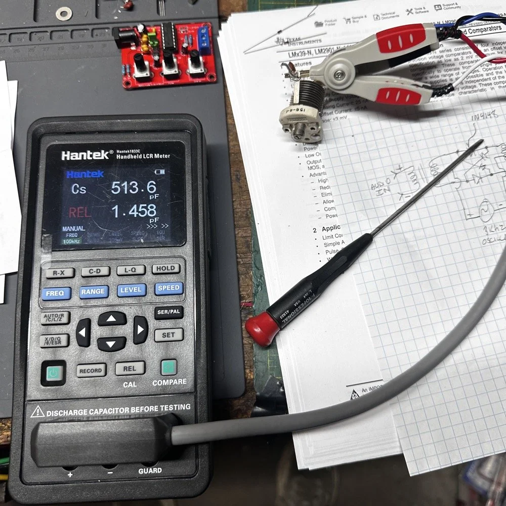
To get the capacitance, I soldered a 560pF capacitor across the 10-70pF trimmer capacitor. The 560pF actually measures 490pF so this with the trimmer gives me a decent working range. I used my Hantek LCR meter to measure the inductor and capacitor before I built it out. The REL in red letters means I “zeroed out” the display prior to testing the parts to remove the inductance and capacitance from the meter leads. I tried a few iterations of the same piece of magnet with to get it to 330nH and it required a toroid to get it to that level of inductance. Without the toroid, I was only able to get about 95nH max out of it. It is also a lot more stable with the toroid core too. So there is that. I am pretty sure this core is not really rated for 50 watts, but we will see. I figure I will call QRL and then “test” on my call for a minute, on a higher band where it is usually a ghost town, and then go out and see if the core is hot. I hope it can handle all the stress I am about to put to it…haha,
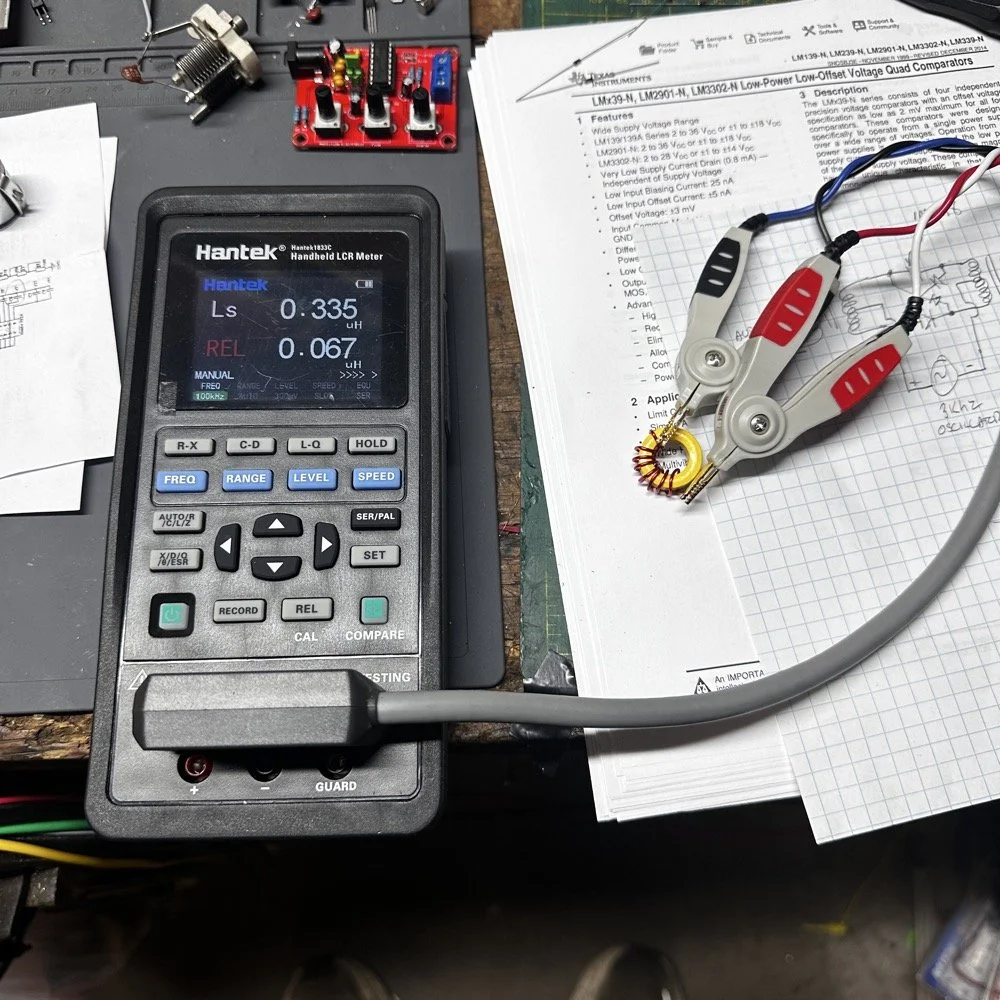
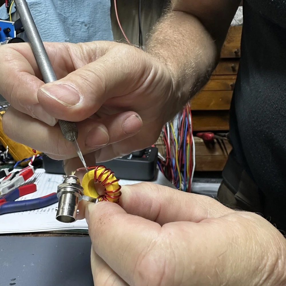
This has been the easiest way for me to get the enamel insulation off of magnet wire. I simply scrape it off with an Exact-o knife. I tried burning it off but it makes a mess. I also tried sanding it off and this does work really well, but it is hard to do and slow. So I scrape them. I dead bug style built this one as it is simply me playing with the idea and wanting to see if my math actually works like it is supposed to. I am fairly certain that it will work, I just want to see if I can get it to do it in the real world too. The SWR was completely usable the other day and whatever it was, so don’t think this is needed for the setup I was using. We are learning here.
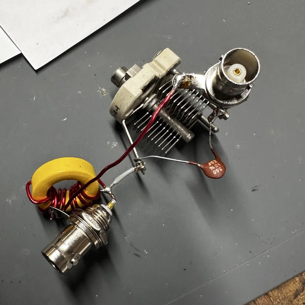
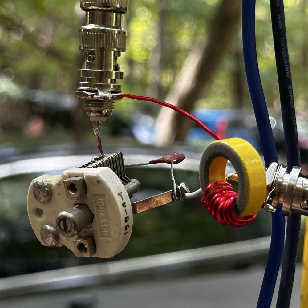
Here it is. I simply used another piece of magnet wire to connect the grounds from one socket to the other and then simply soldered the rest in place. This will have all sorts of stray capacitance issues but as long as I get it to sit still, I should be able to tune it to the setup for the next outing. It will vary a little from one day to the next so this is why I used a trimmer. Also the toroid is adjustable somewhat too. By spreading out the turns on the core, I can lower the inductance some, so this should work pretty well. The cap is technically out of tolerance (and this is probably why I was able to get them on eBay so cheap too) but the measured value was just what I needed for this project.
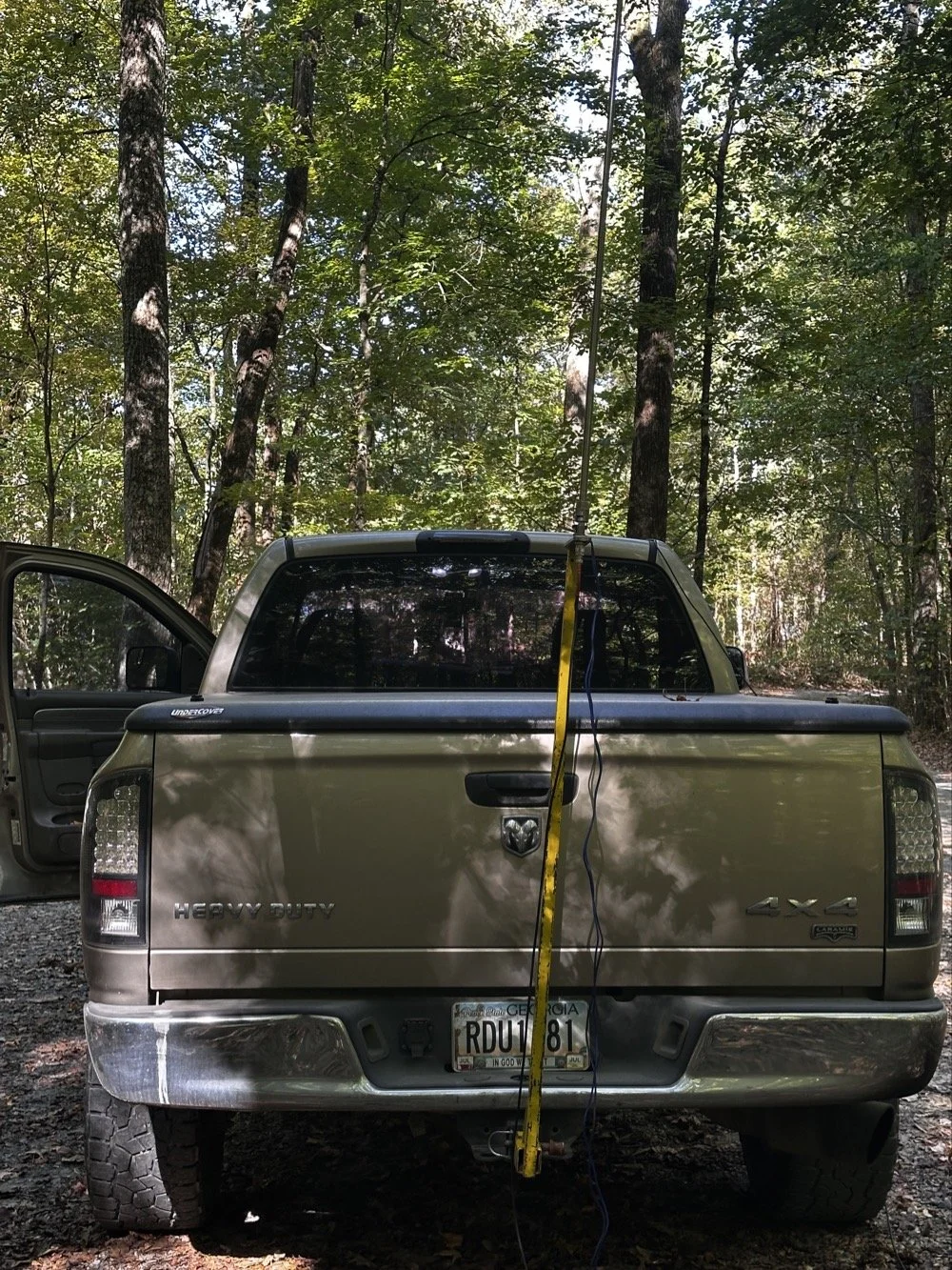
So the antenna on the first trip out for this test, was leaning over to the right. This was so it would not touch some tree leaves near the top of the antenna. This problem will be going away soon as we are entering fall… So this is the setup I need to replicate when I perform my test. Lucky for me, I took a photo of the nanoVNA before I took it apart so I can see when I get it close.
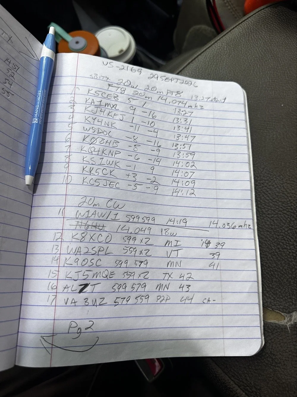
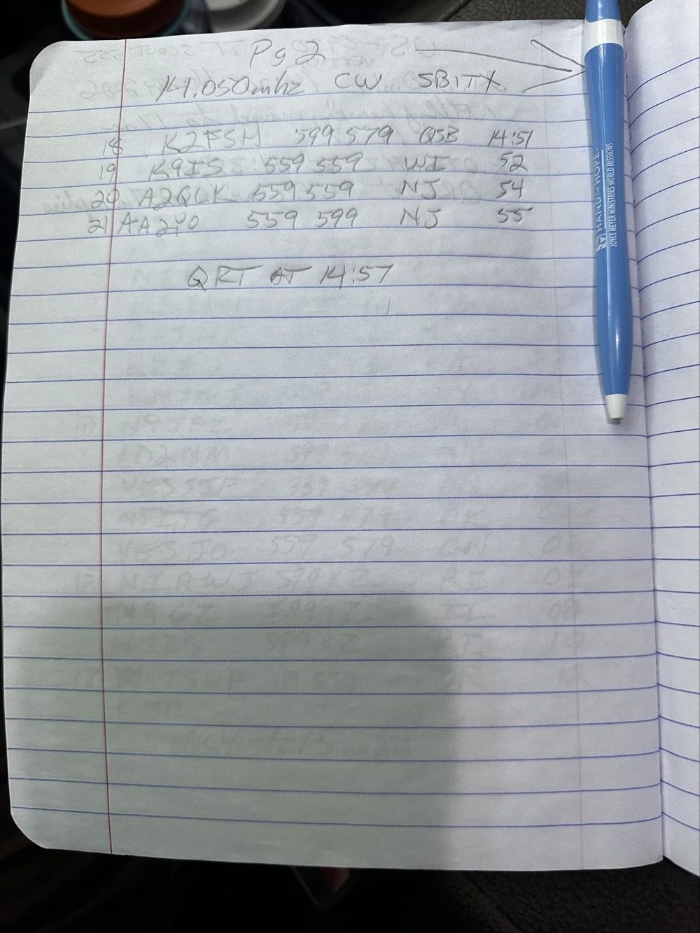
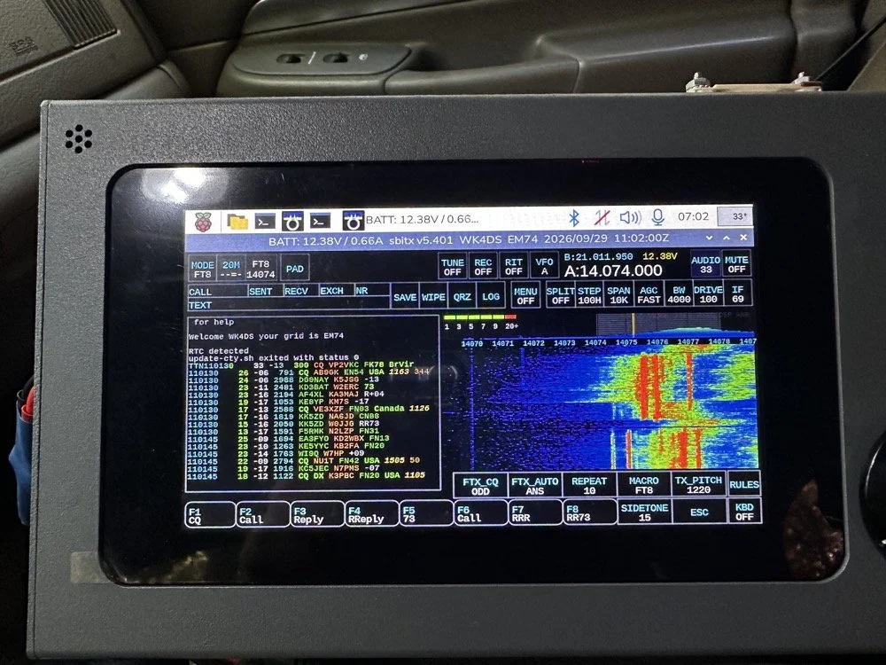
So today I wanted to use the sBitx and see how many FT8 contacts I could get before I switched over to CW. The mini-goal was to secure the activation with just FT8 today then do what ever. Well, as you can see, that was a win. Then I wandered around the band a little and found W1AW and got them in the log next. QSB got to N6HU before I could work them… After that I was able to work several more before I ran out of time. It was a great day at the park! Come back next week to see what happened with the antenna tuner I built!
This latest version of the sBitx OS is really good. This radio was really economical when you consider what your getting. It is only 40 watt, (mine is the early version with the 40 watt amplifier and not the 25 watt version that ships now). It does have a pretty inefficient amplifier design as it loses output power the higher you go in the ham bands. But you know what? It will operate FT8 and FT4 natively INSIDE the radio with no other gear needed. That in itself is amazing!
Today is the day of the big test to see if my math works. I took this amalgamation to the park with me so I could replicate the setup and get it back to as close to what I had as possible the other day. I even parked in the same place. I simply used a BNC to BNC adapter to couple the two bulk head connectors together. This allowed me to connect the matching network to the base of the antenna. You can see both the capacitors and the inductor in this photo and now I have them wired. This should be close to 50 ohms impedance and will probably need a little adjusting on the trimmer cap and maybe moving the coils of wire on the toroid. Other than that, it should be good to go.
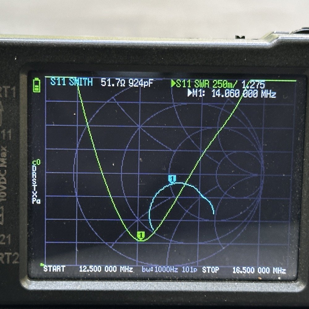
These two photos show what the system looked like before I added the matching network I had made and the lower image is after. As you can see above, the SWR plot looked really good with the impedance being really good. It was close to the other day as well so I should be able to adjust the L network to clean this up some more too.
What you see below is the result after I added the L network to the system. The plot is now over 2 : 1 and the impedance is inductive finally. I have had these be capacitive in nature for a very long time and it was good to see I had moved it to the inductive side of the graph. This tells me that I am on the right track. You can also see that it lowered the resonant frequency of the circuit too. Now what could have caused this? I was needing it to move the graph to the center of the chart and we ended up with this mess instead.
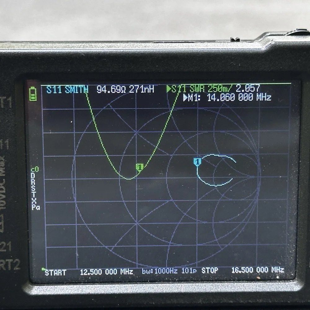
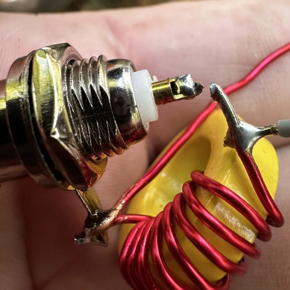
So now it is back to the drawing board to figure out what I did wrong. I am not sure what has happened here. Maybe I measured my components wrong. Maybe I wasn’t setting up the nano VNA correctly. Maybe I did the calculations on the Smith chart wrong… All I know is that it did not work like it was supposed to.
I am going to re-solder the broken solder joint you see in the photo above, then re-test the circuit. Maybe it was a bad solder connection that was causing the error. I really don’t think it is though…
Sometimes you win sometimes you lose sometimes you make a mistake, this seems to be one of those times…
You can help support this channel by using these Amazon Affiliate Links as well:
QRP/Portable Radios:
Antennas & Tuning:
CW Equipment:
Power & Accessories:
Organization & Transport:
BONUS ITEMS (Optional 16-20):
73
WK4DS-David

POTA problems with the TenTec Scout 555
After a solid hour, I got my 4th call. Now what you are not seeing here is the part where I went to 17 meters and called CQ there as well. That was also in that 30 minute block between the third and fourth contacts in the log. I actually thought I would make a few contacts on 17 meters as it usually is open if 20 meters is open.
This activation was very enlightening. I went to US-2169 since it is close to home AND diesel fuel is over $6.00 per gallon currently. I setup at my favorite place in the park, the Frisbee golf parking lot. This place is usually empty on Friday mornings and today did not disappoint. There was one other car that is not in the photo that a group of day hikers exited from and promptly entered the tree line. I never saw them again… I setup in the same spot I like to use, but to be fair, I think I like the spot on the other side of the lot better. This one it the first one I chose, but it really isnt that great for stringing an antenna. I almost have to use the telescoping vertical on the truck mount. The trees near the truck will hold a wire but relative to the truck (read that as to the radio as well) the wire is almost horizontal. This is not ideal for a wire that needs to be above the grade and I assume, the radio…
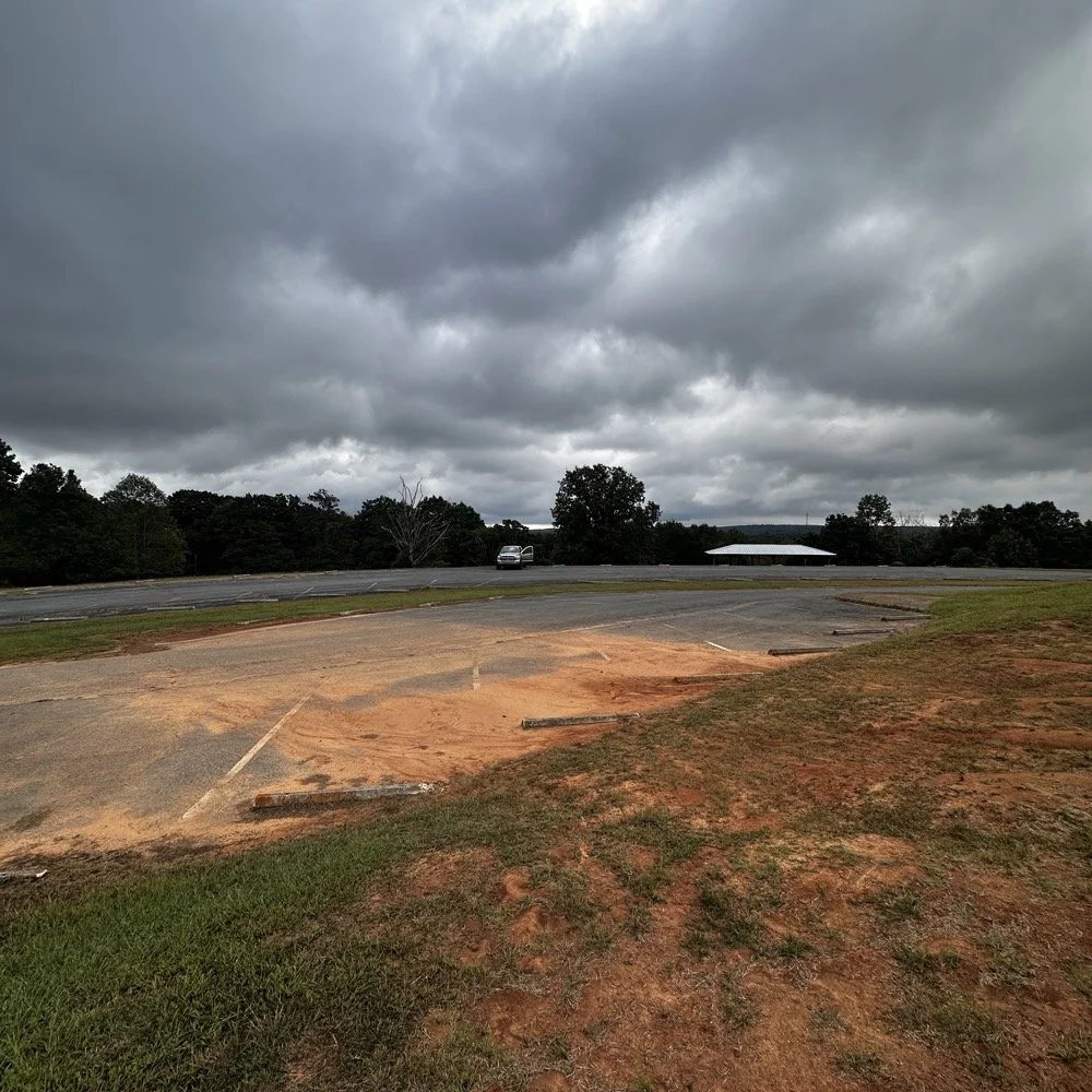
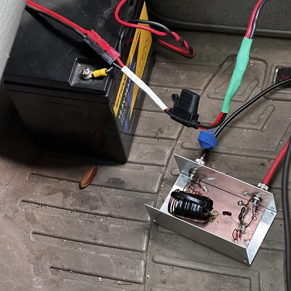
See what I mean about going on the “off” days? I had the place to myself for the most part. Without another soul in sight I was able to leave the doors open so a breeze blew through the truck and made for a pleasant activation. I setup the TenTec Scout 555 in the passenger seat like I usually do since I wanted to use “truck power” to run my radio. You see, I have a cable fed into the cab of the truck that is directly connected to the battery with a fuse and the other end has a power pole connector on it. This allows me to run my radios in the truck with having to hard wire all of the them. This is nice, but as I found out today, it is also a liability…
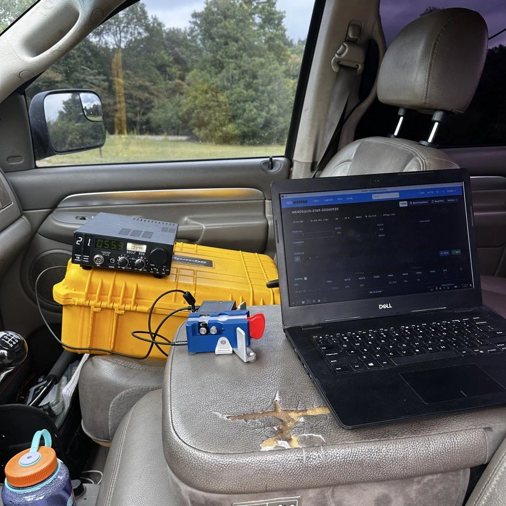
I have gotten very comfortable using this station location. As long as I operate by myself, this works almost perfectly for me. I do wish that the armrest could be longer so that I could more easily sit in the seat and log contacts. As it stands I now sit somewhat side ways a little so my arm can work the key with it at the front edge of the arm rest. I have thought about getting a sheet of plywood and covering the back half with cloth and letting it become the surface when I am operating, that would give me a table for the computer as well as the key and keyer. You can’t see the power cord in this photo as it is run under the yellow case, but it is there. At this point, I had already moved to 15 meters after calling CQ for over ten minutes on 10 meters without as much as a chirp coming back to me. I had high hopes too. You see, when I powered up the radio, I had planned on simply hoping on 20 meters and working on an activation since the signal report looked real bad for today, the K Index was a 4 and the bands only showed Fair from 30 through 15 meters and poor everywhere else.
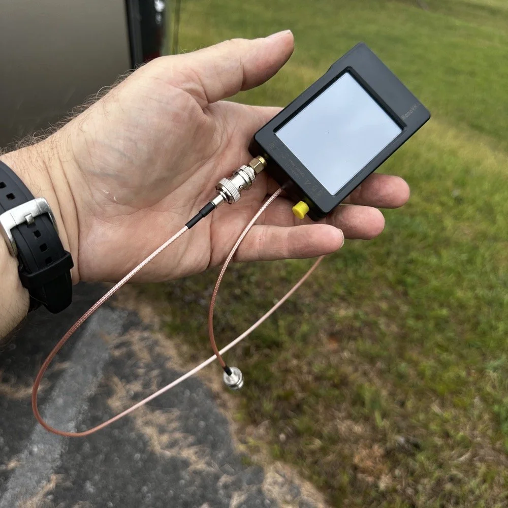
Finally picked up a shorter cable for the nanoVNA to tune the antenna with…
This did not inspire confidence to say the least… But I had the 10 meter band module in the radio so I just hooked it up as it so I could get the circuits warming sooner. The TenTec Scout 555 is a great radio but it had some analog stuff…well…a lot of analog electronics in it and they don’t work properly when they are cold, your frequency will drift while your using it and all sorts of shenanigans. So now, I setup the radio first, get it under power so the idle current can be warming it up and then work on the antenna. I built up the antenna and as soon as I connected the coax, I could hear a station calling CQ! When I looked at the radio, IT WAS ON TEN METERS!!! Ten meters was supposed to be closed right now! Well ,I had just tuned it to 20 meters so back out to the antenna I go with the nanoVNA and tune it up for 10 meters. I get back in the truck and he is still calling CQ! I start answering him and it takes him probably 6 tries to get all of my callsign as I am only running about 40 watts and the band is closed for Christ’s sake. First call in the log today is CX2UI from Uruguay! I am thinking this is about to be a really good day with a lot of calls in the log! Well, it wasn’t. As you can see below it was almost 30 minutes from the first call on 10 meters to the 2nd call on 15 meters… 15 meters was marginally more successful with me landing a whopping TWO calls on that band! Now understand, I dialed up the FT8 watering hole and there were a ton of ops there. If I had brought the sBitx V3 then I could have easily gotten the activation on that mode on ten meters. There was a ton of people there as well. I just wanted to work CW today so I didn’t bring the FT8 radio with me. Constraints like this will make you work harder as it is more of a challenge to get the activation if you dont have easy mode (FT8) available to fill in the gaps. The logbook is upside down as this is a screenshot of HAMRS and that program pushed the call log down and puts the most recent one on top as you go. After nabbing the two calls on 15 meters, it was like the band simply turned itself off to CW use. I tried for almost 30 more minutes to get another contact but nothing was there.

After a solid hour, I got my 4th call. Now what you are not seeing here is the part where I went to 17 meters and called CQ there as well. That was also in that 30 minute block between the third and fourth contacts in the log. I actually thought I would make a few contacts on 17 meters as it usually is open if 20 meters is open. Well, it turns out, 20 meters wasn’t doing great either with heavy QSB on pretty much the entire log today.
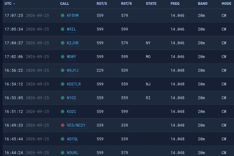
20 meters to the rescue… As you can see, the log is filled out with a lot of 20 meters QSOs. The remains calls only took 40 minutes to get in the logbook. The very last one was a ham that simply answered my call and we had a short ragchew. He also told me that my radio had a birdie or it was chirping when i was sending code. I had noticed that a few minutes into the 20 meter portion I started getting numbers in the 3rd position that were not good. You see, that third number will, pretty much by default, always be a 9. When it is not a 9 then your radio is not working right. I got several in a row with less that a 9 there. That threw me a curve ball as I don’t normally get those kinds of reports. Armed with this knowledge, I took the radio home and connected it to the antenna in my house.
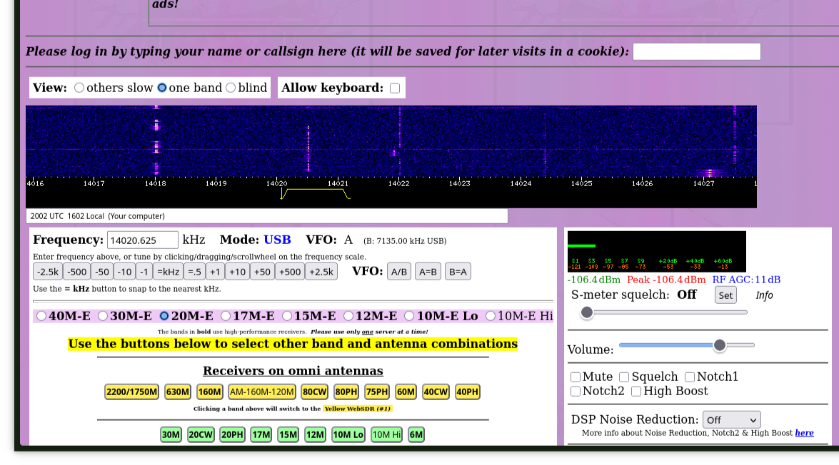
Something I learned from HamRadioCrashCourse on YouTube is that you can dial up these webSDR receivers and test your radio by listening to your signal as it is received by another radio. You are not getting the audio from inside the radio. This is the actual signal that is sent out of the radio, over the air, and heard by another radio. This is the truest test of what your signal will sound like. So I dialed up a portion of the band that had very little use as you can see in the waterfall. Once I found a spot, I adjusted the filter to cut out adjacent signals and then started sending. My signal is the one in the center of the little yellow filter area on the waterfall. The sound coming back to me was perfect too. I listened for a while and it is a little disorienting since there is a delay between you sending and you hearing it. The best way I can tell you to do it is to send your callsign and the word “testing” with the SDR volume turned down and then turn up the volume and sending whatever so you can hear the sound of the signal, and then when your finished, send de Your Callsign and then QRT. It is fine to send a test signal as long as you are not interfering with someone else and you ID your signal. I can not find it anywhere in the rules that this is not allowed as long as you do those two things…well and you know, stay in the allocated band space and don’t exceed the power limits and such as that but you get the point. It is kinda cool to be able to hear what your actual signal sounds like on the air by another radio almost 1500 miles away.
So what did I learn from this today? I learned that the radio isn’t always the problem even if the signal is terrible. Turns out that my cable has a bad connection in it going out to the battery and I was having voltage dips when I would key the radio. I could even see it with the meter lamp dimming on each character during transmit. So I plan to replace that cable with a much larger one on the order of either 10ga. or 8ga copper wire with soon. This and a new fuse holder should get me back up and running in fine order.
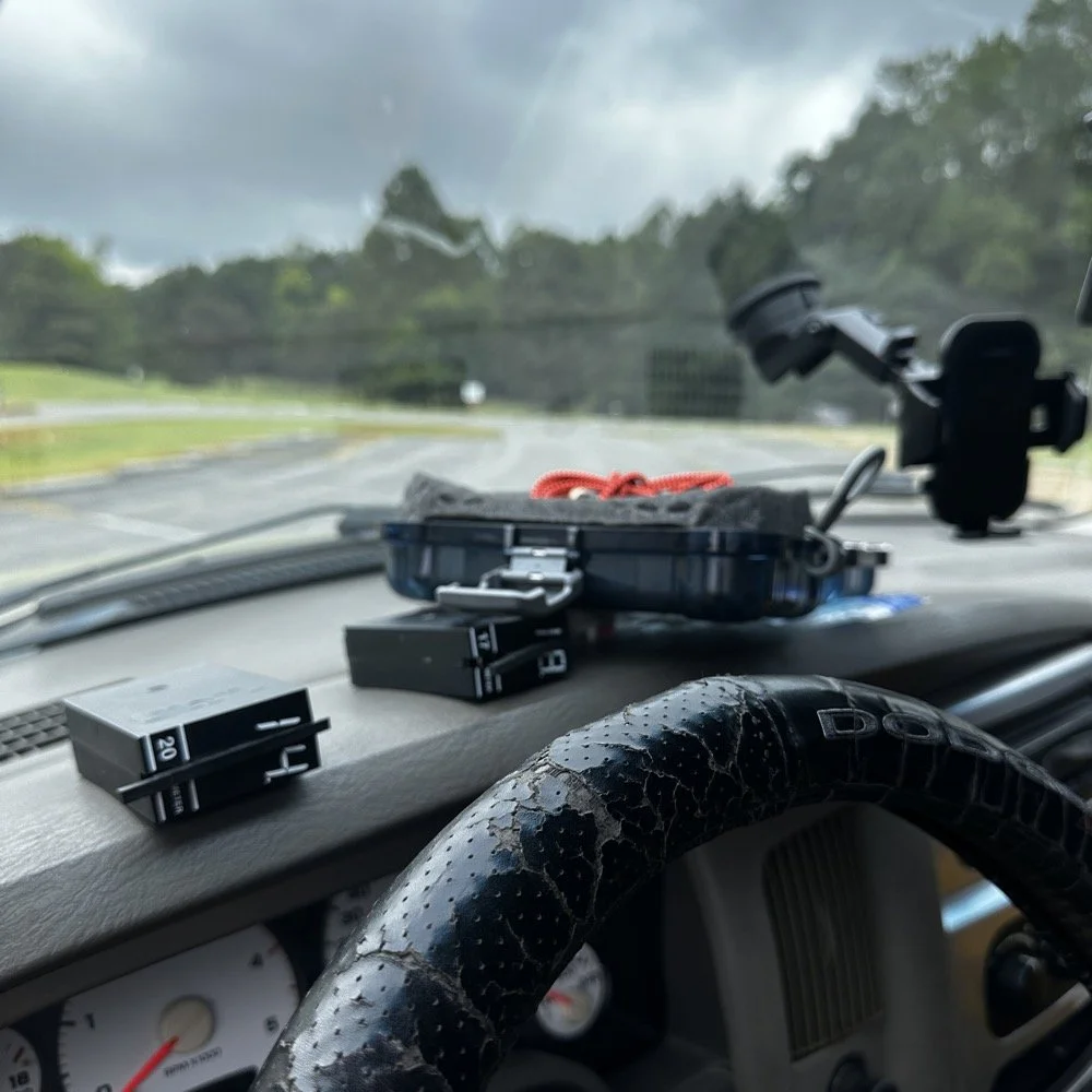
Towards the end of the activation, things were all out of sorts and I had to take my time to get it all cleaned up and put away properly. I will usually get out all the band modules I plan to use that day and just lay them on the dash like you see here. it makes it easy to change bands and I can see all of them as well so I don’t lose one in between the seats or something like that. The case for the Begali Traveler key is laying up there with them too, but that just happened to be the best place for it today. It normally ends back up in the carry tote but today it was on the other side of the truck and this was easier…haha. All in all the day went pretty well considering the Sun was mad and I had a radio that was sending trash for code. Moving forward, I plan to make several improvements to the system as a whole and see if the radio will work even better. Have you had a day when there was a comedy of errors to contend with? Today must have been my day as I have not been out since early August to a park at all and I had started to miss it.
You can help support this channel by using these Amazon Affiliate Links as well:
QRP/Portable Radios:
Antennas & Tuning:
CW Equipment:
Power & Accessories:
Organization & Transport:
BONUS ITEMS (Optional 16-20):
73
WK4DS - David

My 17 meter band pass filter and POTA…
Today I met up with some other hams that routinely go out together and activate POTA parks and was able to fellowship with them for a while before and after I made some contacts. There was (Jonathan Frye AA6H, Allen Padgett KN4FKS and Danny Wooten AG4DW) and they were running what appeared to be FT8 and SSB stations today. Allen and Jonathan were operating SSB the whole time and made quite a few contacts themselves. It was kind of neat to plug in the nanoVNA and see one of the other stations transmitting and messing with my antenna reading and when they stopped I could see the graph again! HAHA!
I built this band pass filter after having a couple of activations with my friend in Florida, Chas (NA2B). We were is such close proximity that if I didn’t have a bandpass filter for the band I was working, I simply couldn’t hear. The sBitx is notorious for front end overload and when the antennas are just a few yards apart, you are going to get front end overload! Well, on the bands that I had bandpass filters for, I had no issues, it was only the bands I lacked filters that I had a problem. It is pretty easy to find bandpass filters for the non-WARC bands, but WARC bandpass filters are kinda rare.
Well, I never let that stop me before…haha. A while back I went down the rabbit hole of wanting to make my own bandpass filters and I figured I would start with the 17 meter band since it is harder to find. I now own a spectrum analyzer with a tracking generator so I can sweep the filter in real time to see what tuning does to the filter shape. That is kinda awesome in its own right, but you could easily do the same thing with a nanoVNA too.

So here is the current iteration of the 17m bandpass module I built. IT sure looks like I home-brewed it, doesn’t it? HAHA! That big inductor It is a classic Pi design with an inductor and capacitor in parallel to ground at the front and back and a series inductor and capacitor in the middle. The input capacitor is underneath that massive 5.31uH inductor in the middle.. I taped it to keep the coils from moving around while I tuned it and then put the ziptie on it to hold the coils in place once I got it like I wanted it. I pulled the values for this filter from the internet off of one of the many website calculators that are out there…I don’t remember which one though… It has been a minute…haha.
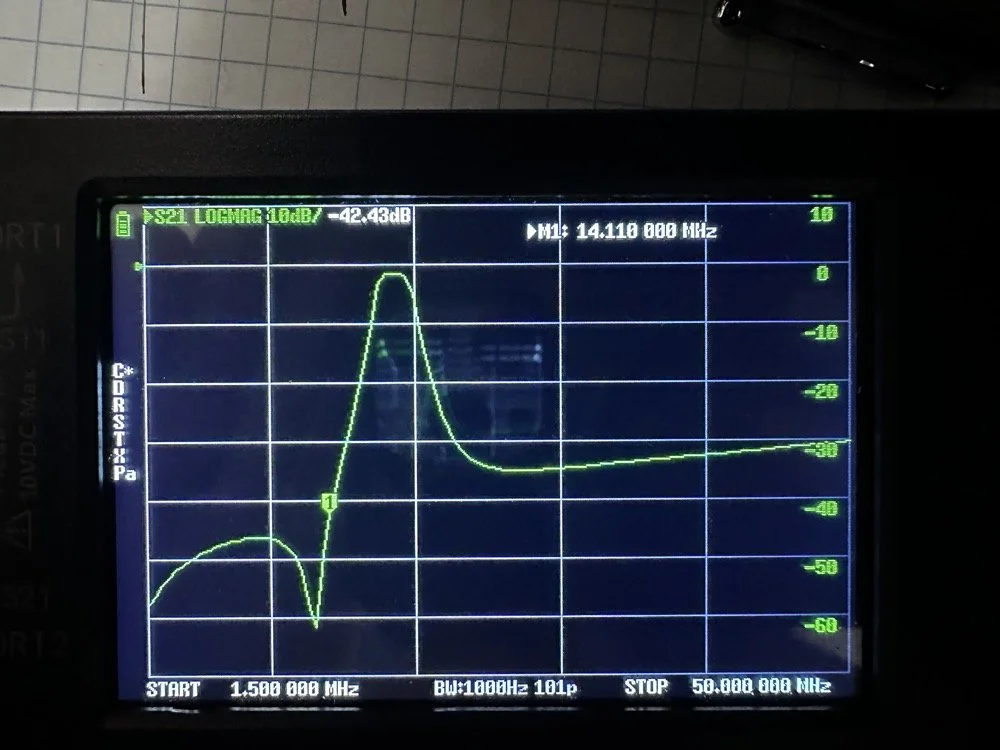
Adding this filter literally stopped all the 20 and 40 meter signals that I had from my neighbors today. It isn’t even all that great of a filter, it does have decent rolloff, but it isnt some knife edge vertical skirt filter. I grabbed a quick photo of the plot on my nanoVNA with the marker on the 20 meter band. I have a little more insertion loss (mine is 1.3dB as compared to a commercial unit at about .65dB), but it works almost as good as one that would cost 200$ and I have about 10$ in it. The filter was even better on the passband before I put it in the chassis. Since I used open air coils, they are interacting capacitivly with the aluminium body to ground. This added capacitance increased the passband insertion loss about .6dB, but it is so clean, I chose to just leave it as is and use it for now. The 20 meter band being over 40dB down compared to the 17 meter band, I was able to setup right next to Danny, who was on 20 meters at the time, without him coming into my radio at all from what I could tell. All the lower bands past 20 meters are lower than that too, so all of them are pushed out of the way so to speak. The higher bands are interesting to me. Before I mounted the unit in the aluminium chassis, it fell off on the high end too. Once mounted it looks like it is about 35dB on 10 meters and about 20dB on 15 meters, which is still good. Another problem that I encountered wtih the added capacitance is that it moved the passband up some. I had it to where the high side of the passband was right at the end of the 17m band before I mounted it. This gave me more attenuation on 15 meters, by probably 6dB or so, but you use what you have and move on with life… This would have also raised the 20 meter rejection some as well, by probably about 6dB or so.
This band pass filter project looks really simple.. The aluminum box, the two BNC connectors, some 16ga magnet wire, three capacitors and a piece of pc board material for a build plane and I am good to go. I lost the lid to the aluminum box hence no cover, but it appears to work just fine like this so I used it. It turns out that if you use toroid inductor cores, that this is a lot easeier to build as the toroids are LESS affected by the chassis ground plane. Notice I said less… they will still change values, just not as much as air wound inductors like I used here. I deliberately chose air wound inductors due to their high Q, which is what gives me the sharpness to the skirts you see in the plot below. I have it marked with “IN” and “OUT” but I honestly think it doesn’t matter which way it is inserted into the feedline as long as it is there. Another benefit of adding a passband filter is that is works both ways, it keeps out stray signals from strong nearby sources and it also only lets the part of your signal LEAVE that will fit through the passband. This makes a huge difference in your signal purity as you are adding a filter to the output of your radio.
Today I met up with some other hams that routinely go out together and activate POTA parks and was able to fellowship with them for a while before and after I made some contacts. There was (Jonathan Frye AA6H, Allen Padgett KN4FKS and Danny Wooten AG4DW) and they were running what appeared to be FT8 and SSB stations today. Allen and Jonathan were operating SSB the whole time and made quite a few contacts themselves. It was kind of neat to plug in the nanoVNA and see one of the other stations transmitting and messing with my antenna reading and when they stopped I could see the graph again! HAHA!
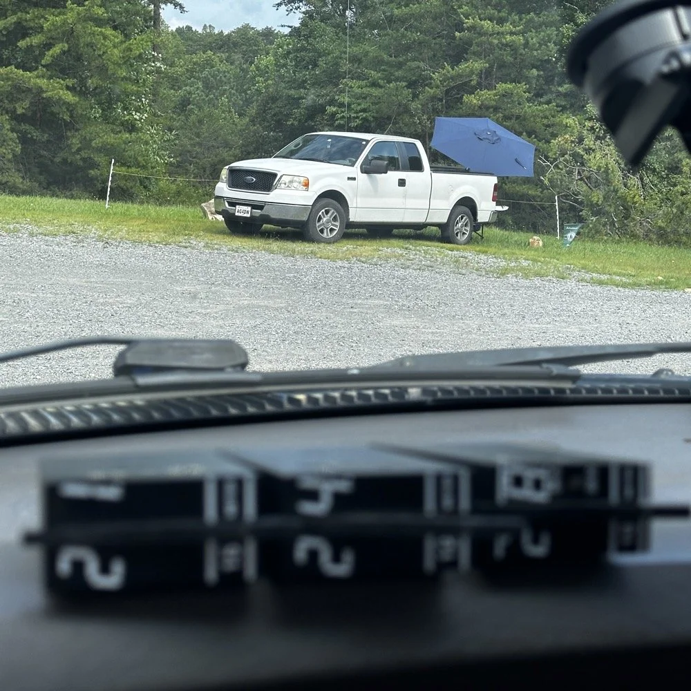
You can see the antenna right behind Danny’s (AG4DW) truck looking out the windshield of my truck today and I moved as far away from the other people as I could muster without driving in the yard… This area is really small to be fair. It just doesnt have a lot of room to setup too many stations. In reality I was probaby the last one that could fit without too much trouble being caused by other radios. Now that doesnt mean this park is overloaded with three stations. Not at all! There are 5 other locations to set up radios that I can think of right off hand with out even trying hard so we could setup several sites at this park very easily. Now, that turns it into something else thoguh, that might be enough activity to trigger the need for a permitted activity, but I dont know. I normally just hand out wtih these guys or go by myself for the most part so it is pretty low key like that.
Those band modules in the above photo are a precursor to what I did today. I opted to stay on the higher bands no matter what. I knew I could land the activation with FT8 and CW, but I had no idea just how hard it would be…haha. This poses a good challenge though as I know I can easily land the minimum ten QSOs to get the activation if I just start on 20 meters but lately the bands have been up and down and have been real inconsistent on the higher bands so to get my ten would take a bit more work on my part. Challenge accepted!
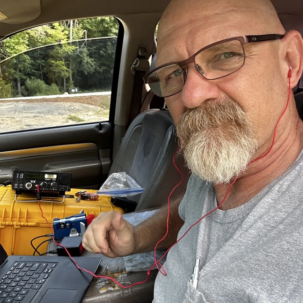
So, natuarally I started on 17 meters…haha. I actually planned to work my way up to ten meters, hence all those band modules you saw earlier. I found W1AW operating CW on 17 meters and busted his pileup to get in their log! That was my first QSO of the day too, I knew right then that it was going to be a good day. As you can see in the photo above, the station was setup in the truck cab to keep me out of the sun as much as possible. I also was using the Begali Traveler key and the HamGadgets Pico keyer as well. Also if you will notice, I dont have the common mode choke installed today. I was testing to see if getting the SWR below 2:1 made using it irrelevant or not. I had really good SWR all day at the radio so I dont think I need this thing adding losses to the system when I was having a good showing on the radio. (It is the thing laying next to the radio in the background.) Do you use one every time you go out or is it something you dont worry too much about? I ran this one through the nanoVNA and it said it had from -.06dB to -.19dB of loss just inserting it in the line. Look at the chart below to see what it looked like across the HF bands for this common mode choke on the nanoVNA.
160m: -.06dB
80m: -.09dB
60m: -.10dB
40m: -.12dB
30m: -.13dB
20m: -.15dB
17m: -.16dB
15m: -.16dB
12m: -.17dB
10m: -.19dB
While this might not sound like much loss (all of them being less than 2/10ths of a single dB), if the bands are in bad shape and you are trying to hear stations near the noise floor, this can make a difference. I routinely listen along the noise floor with headphones for stations that are really weak. Today was one of those days. The bands were really bad for the most part. CW was not being used much because of this. I did get a good run on FT8 on 17 and then 15 meters, but the CW portions were all in the tank.
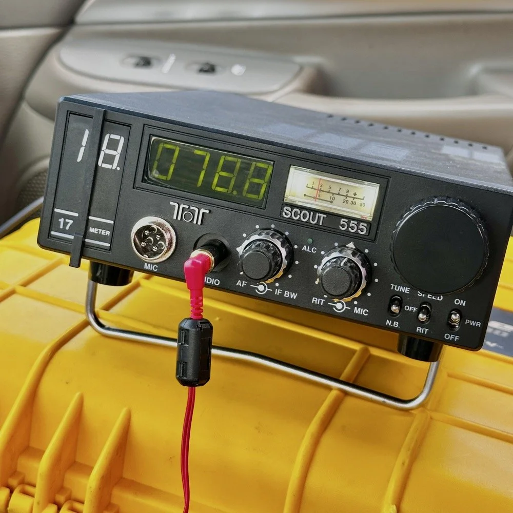
I started on 17 meters as mentioned earlier, I started by hunting a little and found W1AW was making contacts so I worked them first thing. It only took me three or four trys to get them in the log so I was pretty stoked about the day at that. But then it took me 50 minutes to land the 5th QSO in the log! That is super slow for my normal operations. So I opted to switch to FT8 so I could get the activation locked in before I went off on the higher bands playing…
I worked five FT8 contacts in a little under 20 minutes just using hunt and pounce. This had my ten in the log so now the rest are “gravy” at this point. Next thing I did was re-tune the antenna to 15 meters and since the sBitx was already running, I hunted on FT8 there for a while. I netted 6 QSOs in something like 14 minutes. This is actually a pretty good rate for me on this radio so I was happy with that. After landing those in the log, I set the Scout 555 back up and called CQ on 15m CW for a while… I had zero replies… It was like the CW portion was simply turned off. Seriously, where did all the CW ops go? FT8 was booming! I saw a ton of DX on FT8, even though I couldn’t work them, but they were there. Anyway, after calling CQ for like 15 minutes with no replies I figured I would hop on 10 meters and listen for my beacon and then see if I could get at least one QSO there before calling it quits for the day.
It took me about 50 minutes of calling CQ into the void to finally land a contact between 15 and 10 meters. The last FT8 QSO in the log and the one on 10 meters CW are literally 50 minutes apart! That is a lot of calling CQ with no responses. I actually was listening to the radio while talking to Jonathan and just letting the keyer do its thing. When suddenly there was a reply out of the ether! KE2FUA up in New York heard my pitiful pleas for a call and felt sorry for me. Giving me the QSO on 10 meters I desperately wanted. With that in the log, I called QRT and broke down the station. Afterwards I was able to spend some time with the other operators on site and chat with them a little. This is the main reason I love activating with these guys, the camaraderie is incredible.
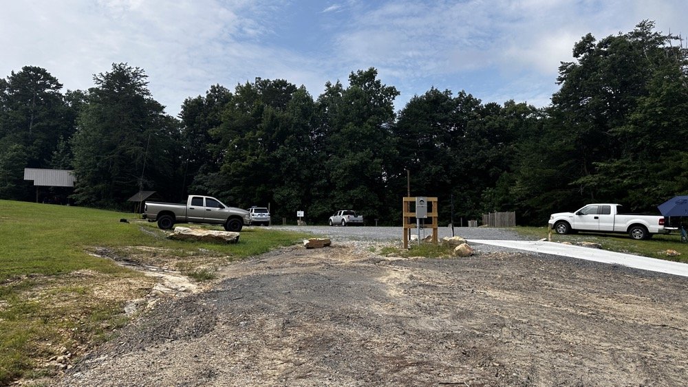
This view shows the tight conditions pretty good. The pavilion in the back has the SSB setup and the white truck had the other station with me kinda in the middle. As long as we used band pass filters or there was enough band space between us, I didnt have a problem. While I was on 10 meters I didn’t have a filter for that band, so I was open to interference and didn’t hear anything from the other stations. I know that at this time, one was on 17 meters and the other was on 20 meters. Band pass filters are a life saver as well as a little coordination between stations. When I arrived, the others were already setup and operating so I went over to each one and gathered some intel about how it was going for them and their current band so I could pick one that they were not currently on. They were both running band pass filters so I was able to start literally anywhere I wanted except 20 and 40 meters. I love the higher bands so that was when I cooked up the idea to do just the higher bands to see what I could net with that sort of restriction. It also allowed me to use my newly minted 17m band pass filter too…
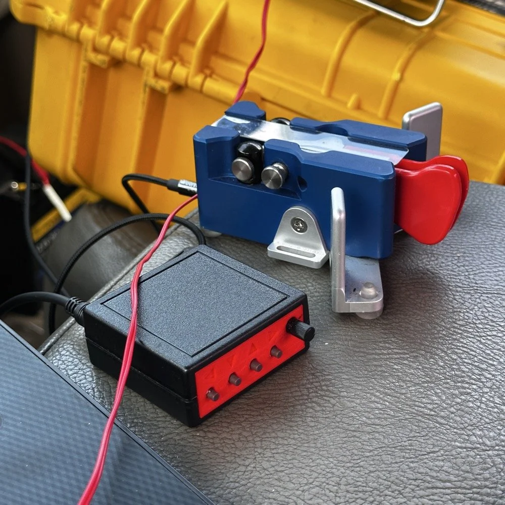
I cant say enough good things about this little keyer. The stark contrast between the cost of each item is not lost on me… I like things the work well and serve me without too much fuss. Both of these tools have done that well. I have finally used the keyer long enough to need to replace the battery in it. Which is a simple task, but does require a screw driver… I thought I would hate having a battery powered keyer, but to be honest, it is kinda nice being able to put it literally anywhere and it just works. I printed the operation manual and keep it in the case with the Scout 555 so if I need to do something in the menu that I dont remember how to do, I can just look it up right quick.
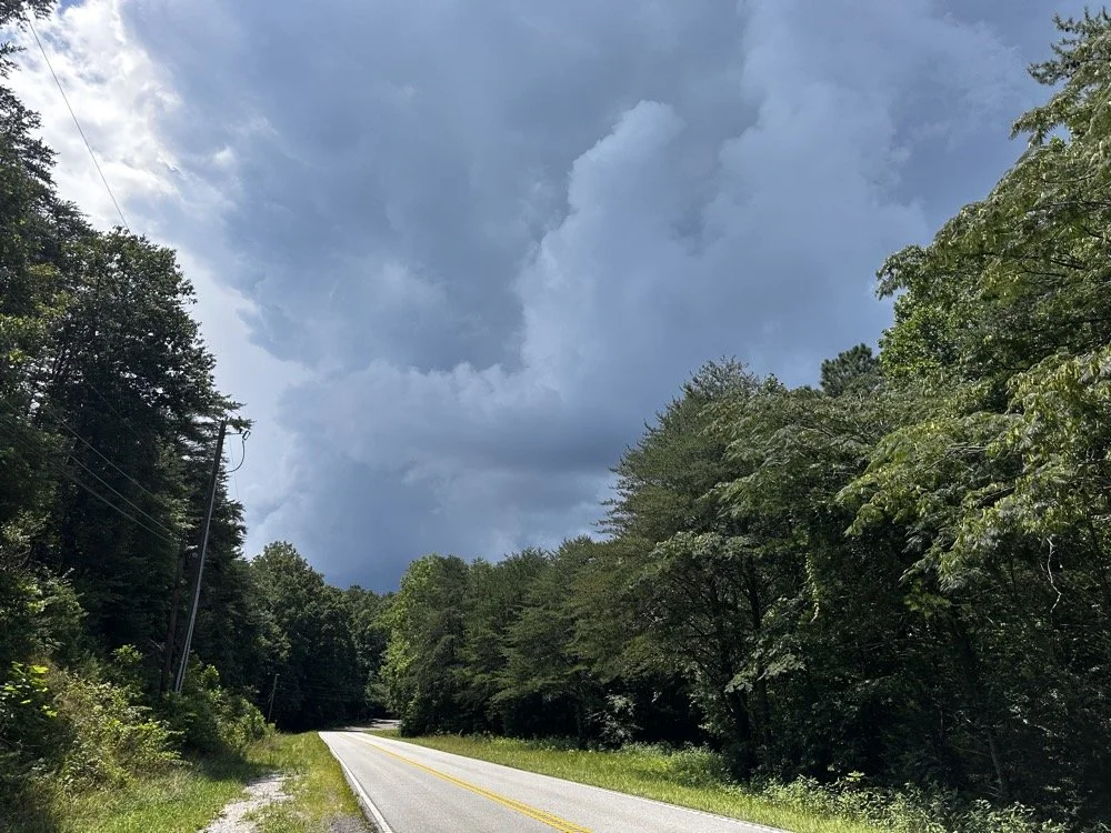
At the end of the activation, I had to break down early and go run some errands and I did itjust in time too as this was what greeted me when I pulled out of the parking lot onto the main road. Sometimes you just get the right amount of things to happen in the right order I guess…
You can help support this channel by using these Amazon Affiliate Links as well:
QRP/Portable Radios:
Antennas & Tuning:
CW Equipment:
Power & Accessories:
Organization & Transport:
BONUS ITEMS (Optional 16-20):
73
WK4DS - David

60m Band Module Part 5: SSB Operation
Getting SSB to work on a converted band module for 60 meters is tougher than I thought. It takes mods in the radio too…or it is not possible at all. One or the other is the fate of this TenTec Scout 555 HF radio and the 60 meter band module project.
If this is your first time seeing this project, please go back and take a look at the full series so you will be up to speed on this project.
- Part 1: Initial Conversion and Filter Design
- Part 2: Crystal Selection and Mixer Circuits
- Part 3: Field Testing and Troubleshooting
The Single Side Band Problem
Today, we are taking a look at the TenTec Scout 555 60m band module that we built and figure out how to make it work on single side band properly. This band module was created by using a donor 80 m band module and from there things were changed and re-tuned to make it work on the 60 m amateur radio band.
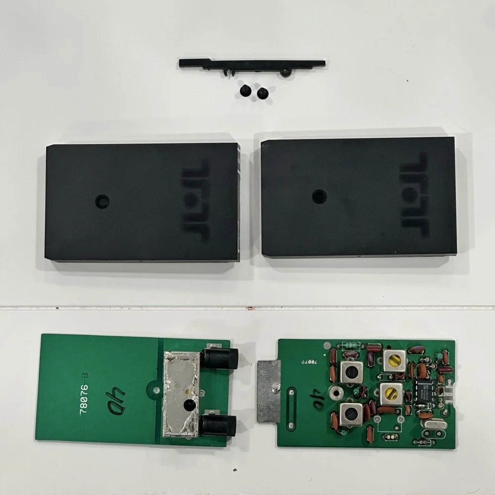
One thing that has turned up though is that the 80 m band module operates on lower side band. To get the side band correctly oriented for the 60 m band I need it to transmit on the upper side band. This is not the normal convention for amateur radio operation though. The normal convention is as follows; bands 30 meters and lower, such as 40, 80, 160 and so on, will use lower side band. All bands 20 meters and above use upper side band instead. Someone a long time ago decided this was how we will do things going forward and here we are. Well for some reason, the 60 meter band is not like the other lower bands. It is using upper side band so I have to figure this out. The next step I have to do is figure out how the radio determines what band module is installed, and which side band it chooses. The radio automatically chooses either upper or lower side band, depending on the band module in use. So something is either telling the radio to monitor the actual frequency or it is looking at the band modules themselves and it is determining it that way somehow. All we have to do is figure out how it’s determining it and tell it to choose something different. Simple enough.
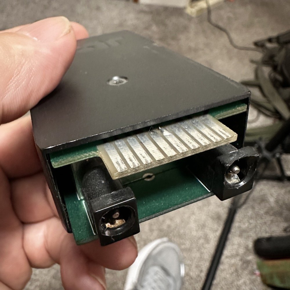
40 meter band module showing the soldered in ground jumper installed on pin 6.
Finding what triggers the shift from upper to lower side band
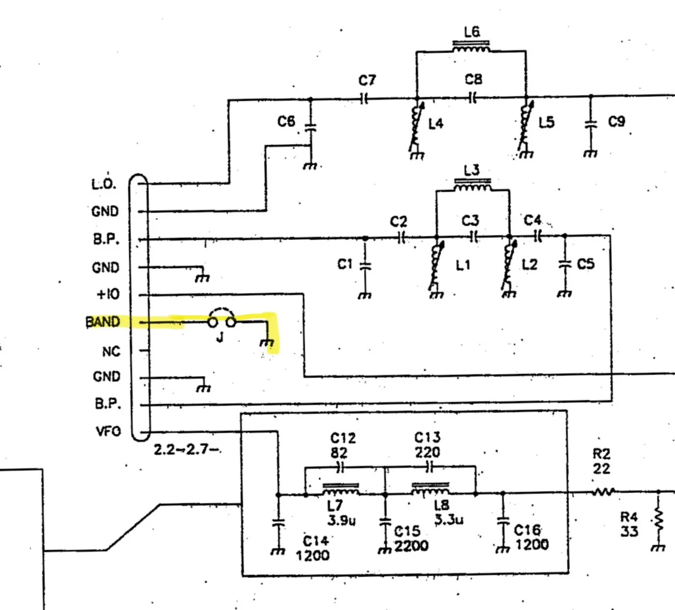
Everything we need to figure this out is in the TenTec Scout 555 owners manual. The manual has an complete set of schematic diagrams on the radio inside. I first start by looking at the band module schematic itself and found that there is a pin marked “band” with a jumper shown on it. This is a very suspicious connection and has me very interested in this particular pin. So this is where I’m going to start my journey since this sounds like it is what tells the radio which band the it is operating on. The next thing I had to do was figure out where it went in the radio, so I dig out the prints and found what follows…
The first image is an exert from the schematic of the band module itself showing pin 6 “band” being grounded with an optional jumper.
Band Module Edge Connector Pinout showing Pin 6 as the “Band” pin.
The next stop for this circuit is the Low Level driver board and it lands on a pin on connector 48.
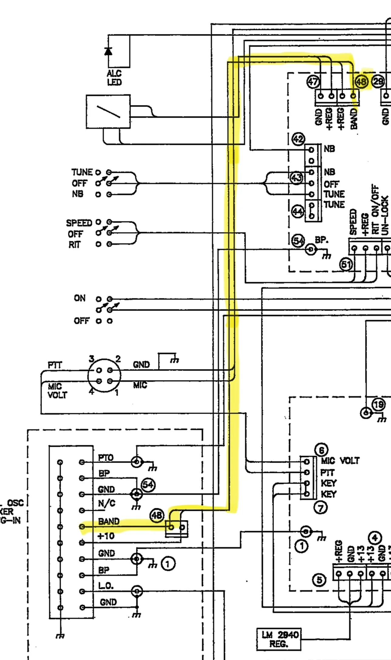
Section of the Low Level Driver Board Schematic showing the path from the “band” pin on the module edge connector up to a pin on cable 48.
It then travels along cable 48 over to the Low Level Driver board.
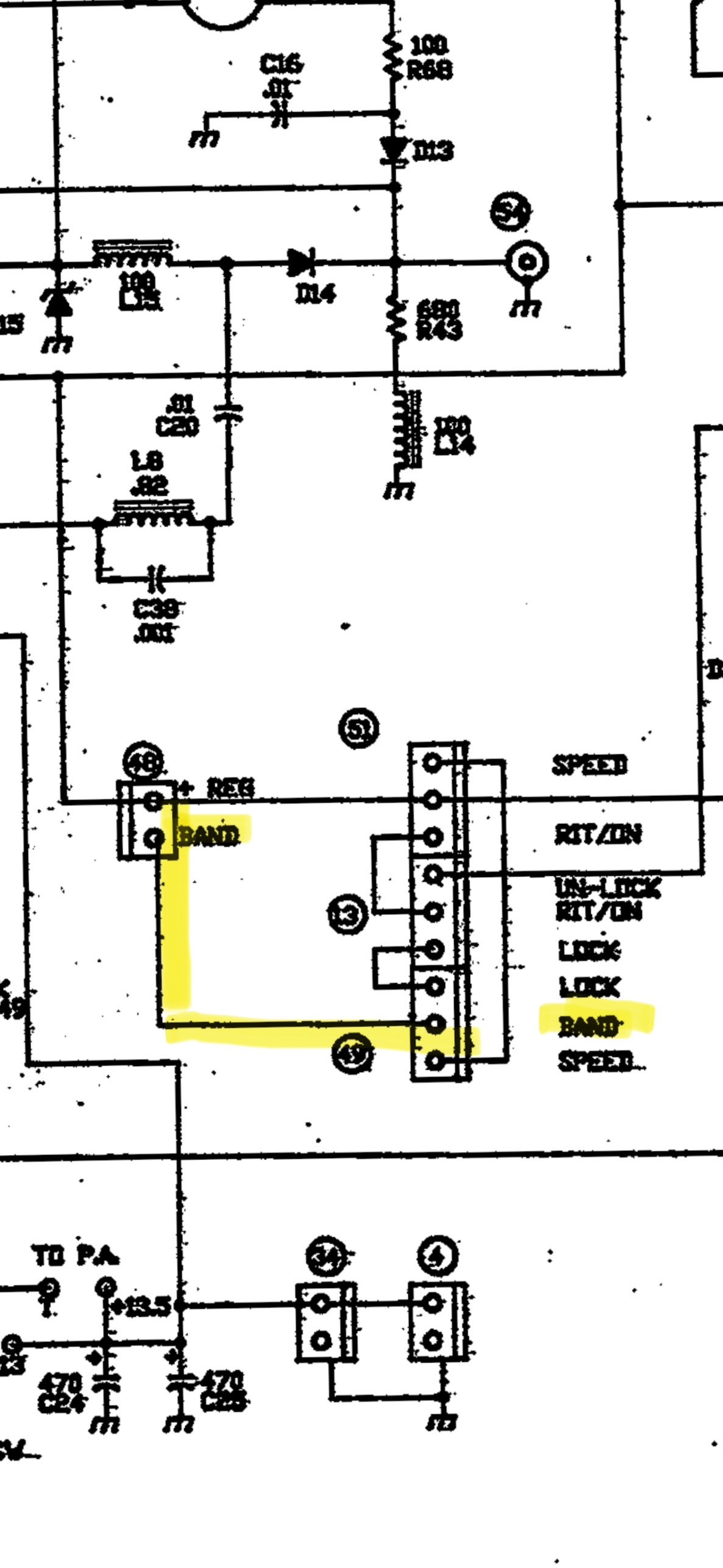
Low Level Driver board wiring showing connector 48 and 49 for the “band” selector.
The next place it went was from connector 48 to connector 49 on the low level driver board where it exited the low level driver board. I am going to be honest here, this wiring makes no sense other than to add two points of corrosion with bayonet connectors that are not needed. There was no reason to goto the LLD board just to exit the board without doing any work with this signal from the band module. Yet, so is life…
It leaves connector 49 on the low-level driver board and goes to the Logic board. Once on the logic board, it goes to pin 10 on the PIC16C57 controller Chip. This chip is probably being used to control all sorts of stuff, but this pin is being pulled low when the band module is grounded and it is being pulled high through R14 (4.7K ohm) resistor when the band module is not jumped to ground.
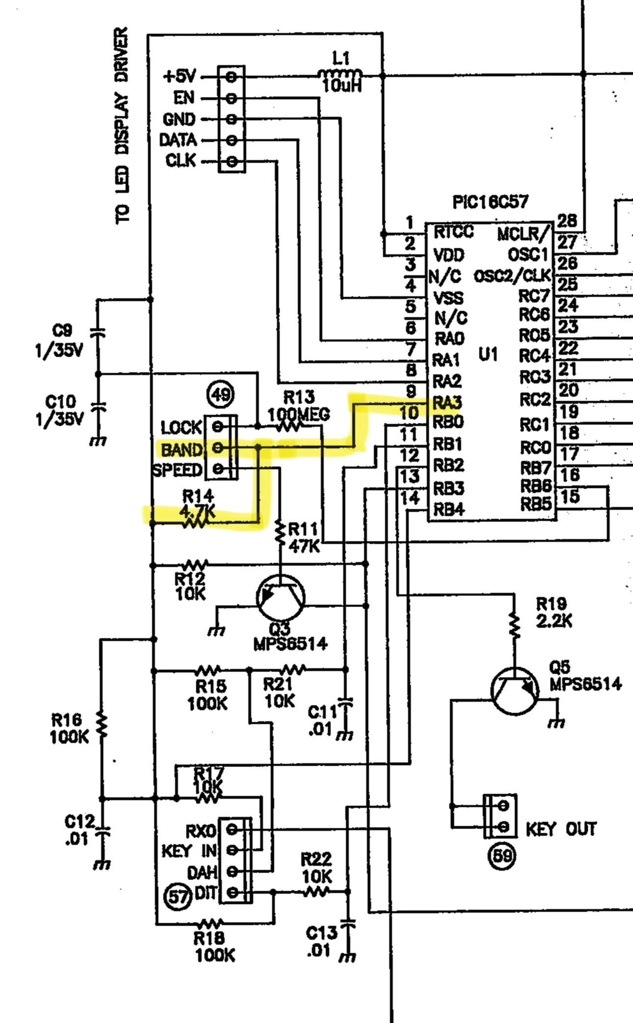
After tracking it down to the PIC controller, I have come to the conclusion that if you pull this line low (tied to ground), it determines one side band mode and if it is left ungrounded, it is pulled high by a pull up resistor to set another side band mode. So I went and retrieved my multi-meter and checked a full set of band modules to see and this is what I found:
10m - open
12m - open
15m - open
20m - open
30m - shorted
40m - shorted
80m - shorted
160m - shorted
60m Single Side Band on a TenTec Scout 555 is hard!
Once I saw this pattern I knew that this was how it knew what each mode needed to be. It had no way of knowing which band, but it knew which side band mode…or so I thought… As fate would have it, I learned something else today. I took my 60m band module to the workbench and de-soldered this ground contact so it would transmit on upper side band. Knowing that I didn’t touch any of the other stuff in the module I merrily trotted back to the shack to test it out.
Turns out more happens with the radio than just choosing the side band… Turns out there is a second thing that happens when you cut this trace. You see when you look at the chart of the frequency path on the NA5M website, you see that 30 meters and below, the 6.142mhz IF is subtracted from the Local Oscillator sum and 20 meters and above it is added. So when I cut the trace, the radio now transmitted on 17.616mhz and not 5.332mhz! Yeah, sure, now I had upper side band but now I was on the other end of the world from where I needed to be… Little good having upper side band does me if I am off frequency by over 10mhz!!!
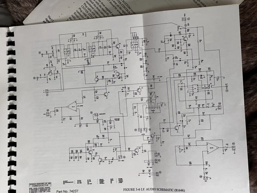
I figured out the following:
The band module has a pin on the edge connector that when grounded, makes the radio operate on lower side band and it subtracts the 6.142mhz IF from the signal. When it is open, the exact opposite happens. So what I need is for the radio to be like a “low band” module for the mixer, but use upper side band for the voice and some of the data modes. This is the problem I need to solve and the answer was on YouTube. After looking at the problem for a while and understanding how the two sidebands are literal mirror images of each other spaced out from the center frequency. I finally found a fellow ham from Australia that had the answer. Simply flip the audio frequencies only and adjust the radio as if it were lower side band. This sounds silly till you see his video. I currently have center tapped audio transformers on the way so I can build a circuit that mixes a 2500hz tone with the audio stream as the audio passes through a diode ring mixer. This will invert the frequencies when it does this. If his video is not fake, I will have solved the SSB problem on the Scout 60 module. Sure it will take an homebrew external converter module, but at least it will work! I have to invert the audio on both transmit and receive so I have to control the microphone input as well as the speaker output. The speaker is easy as I can simple grab the headphone jack audio and process it to a set of headphones or external speaker, but I will have to put microphone connectors on the unit as well so I can intercept the audio from the microphone as well as have it trip a relay when you press the “push to talk” button. All of this should be pretty easy to accomplish so I am confident this will work.
So here is the plan, I want to use that pin right beside the “band” pin on the module edge connector to ground it. Then I can route that to a new plug on the back of the radio to allow me to control a relay with it. This will “enable” the reversing circuit to get the audio corrected for use with this module. Since all the other band modules don’t use this pin, it will only work with the 60 meter module. This is if I have to build the circuit outside of the radio too. If I can get it to fit inside the radio, then I can make the whole thing look original and not need a small adapter to correct the sound and microphone audio. Other wise, I will be piping it through a converter box with the ring mixer in it and a relay to switch the path from transmit to receiver.
The TenTec Scout 555 owners manual has a lot of the information that I need to make this happen, but it doesn’t tell you everything. It mostly describes circuits so you understand what your adjusting it, to trim it back in and get it running right.This means you have to figure out what is going on with the circuits so you can understand how to modify them. This is the hard part for me. For now, at least, the SSB problem remains. I hope to be able to solve it, but right now it looks a little unlikely…unless you know something that I dont and see it in the photo of the schematic above.. haha. If you see a possible solve, please email me or leave a comment and lets talk about it, I am really enjoying this project and would love to get that one last mode to work right.
You can help support this channel by using these Amazon Affiliate Links as well:
QRP/Portable Radios:
Antennas & Tuning:
CW Equipment:
Power & Accessories:
Organization & Transport:
BONUS ITEMS (Optional 16-20):
73
WK4DS - David

Smith Chart Exploration for Ham Radio: Building Impedance Matching Networks with DIY Inductors
Today finds the unsuspecting ham radio op perusing YouTube for something new to learn as it is really cold outside. He stumbles across a video about using a Smith Chart to match impedance and is intrigued…
What happens next is kinda terrifying…lol
Well to be honest, it is really kinda boring till you see how a smith chart sort of works and you start to learn how to use it to some degree. I have known about them for years, but have never understood how they work or even how to read them.
Today finds the unsuspecting ham radio op perusing YouTube for something new to learn as it is really cold outside. He stumbles across a video about using a Smith Chart to match impedance and is intrigued…
What happens next is kinda terrifying…lol
Well to be honest, it is really kinda boring till you see how a smith chart sort of works and you start to learn how to use it to some degree. I have known about them for years, but have never understood how they work or even how to read them. The other day though I landed on a video. This one shown below to be exact and I was hooked.
As you can see, if you watch this video, (maybe a couple of times), he explains it in simple enough terms that I actually understood what was going on finally! I did come into it with the understanding that the upper half was inductive and the lower half was capacitive from tuning my antennas with the nanoVNA. I would leave the smith chart on out of laziness and simply used the SWR graph to move the null to the operating frequency. But during this time, I started looking at the information presented on the display and noticed at times it would show capacitance and sometimes it would be inductance and also where the marker was sitting. This gave me the clue about what it was sharing with me. That was the extent of my smith chart knowledge though. At least it made sense to me. So the next logical thing to do was to order some smith chart notebooks from Amazon and a drawing compass so I could use said charts. While I was anxiously awaiting the new goodies to arrive, I started binge watching videos on smith chart use and taking away what I could from each video to add to what I already knew. By the time the paper arrived (I know I could have printed them off the web but the notebook format is really nice to be honest) {sarcasm}I was already a “master” at these “simple” charts… haha. {/sarcasm}
I will be honest with you. There is so much about these charts that I still don’t understand that it boggles the mind, but I have figured out how to use them for impedance matching and it is kinda awesome. I actually made the last few pages in my new notebook a cheat sheet based on the above video so I could reference it easily without having to watch the video over and over. I am absolutely going to build one of these fixtures when I get back home too. I would already have done it but I am not able to access my bench to put it together… So what follows is what you do when you don’t have that gear handy.
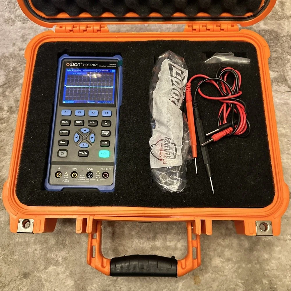
First things first, I bought a new toy. This is a 200 mhz “scope meter” but this one has another trick it can exploit. This is a actual dual channel oscilloscope AND it also has a arbitrary waveform generator as well! On top of the usual multi-meter functions as well. This thing has a lot to offer…till it doesn’t. It didn’t take long to figure out that the waveform generator doesn’t have the sweep function in it, this would have been nice to play with things. I can’t find FFT modes anywhere in it either so it can’t be a “poor man’s spectrum analyzer”. The little meter does have enough options to be really useful for what I was doing anyway so let’s get started… oh, it doesn’t come in this nice hardshell case. This is an Apache case from Harbor Freight. It is the perfect storage container in my opinion and I am happy to have it trimmed out like this. It didn’t take too long to figure out how to use the oscilloscope and I made a cheat sheet for it too so I can access useful features more easily in the future since a lot of it is hidden in menus due to the diminutive size.
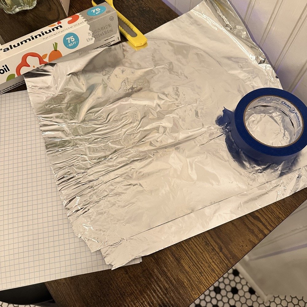
What you see here is pure desperation to see if I can make this smith chart stuff work for me. I am literally about to start making capacitors out of aluminum foil, a sheet of notebook paper and painters tape… Spoiler alert, it worked… You see, in another video I found on YouTube, there was this idea that you don’t need a LCR meter to measure your components as long as you have a known value device, a battery and some ingenuity. I also had a lot of time to play with this concept so here we are… I started by making a really big capacitor to start with to do a proof of concept and to see if there was enough capacitance to make this project work. Turns out there was way more than needed with the initial design, WAY more. So with the proof of concept made from three full size sheets of paper laminated with aluminum foil on one side of each one and then stacked so that the center sheet was one plate and the top and bottom were the opposite plate, I found I had made a .0034uF capacitor! This was more than enough to play with HF radio RF frequencies!!! Woohoo! Now this is all based on me being able to believe my new meter and later I find out that there is 17pf of stray capacitance in my meter and leads. Once I figure this out, and factor it into my math, it is all good but for now with this thing being 3408pf, I don’t think it is really a problem. The cigar box is there to use gravity to apply an even pressure to the “plates” and hold them at a consistent spacing as at this point, these were just three sheets stacked up. The top and bottom are connected to the black lead and the middle one is connected to the red lead. Also tested it with just on plate on the black lead and yep… capacitance went WAY down, so this style of capacitor worked pretty well to be honest. I could make it go up a good bit more by pressing on the cigar box too, I saw 5.0nF at one point while playing with it, that is crazy to me…
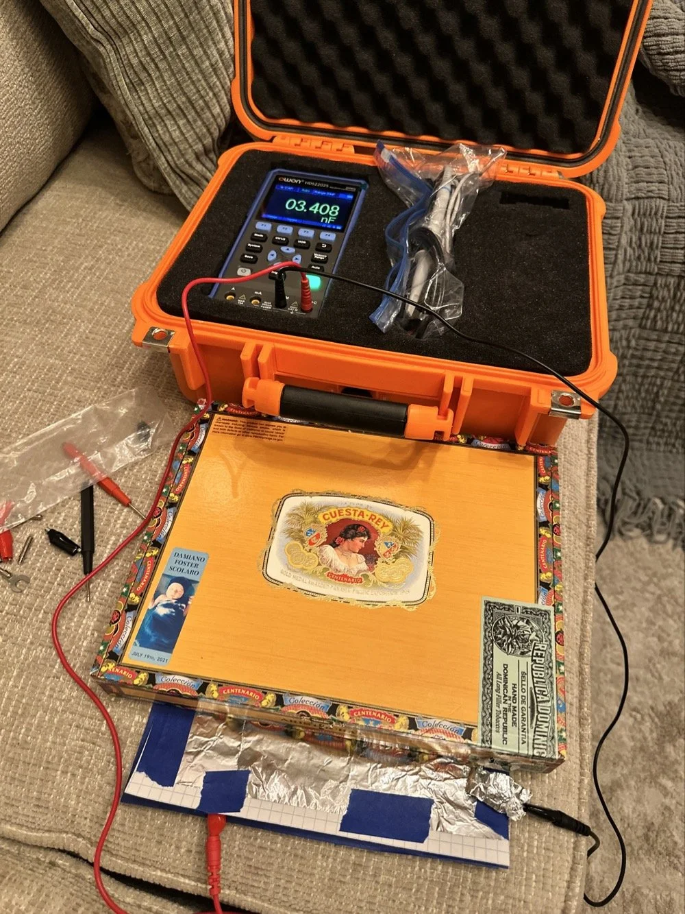
I had read somewhere about this idea to be honest. Well a cruder version of it actually. They made an impromptu antenna L network with two sheets of aluminum foil and a sheet of news paper or something like that. That made the capacitor and the inductor was wound on something found commonly in the house in the 1960s or 70s as well. They just used regular old romex house wire to make the inductor and it also worked just fine. Sometimes you just really need to have some “want to” and it can be done. I was a little more superfluous with my build as I didn’t need it to get on the air but rather as an experiment to see what I could learn.I honestly was really surprised to see how much capacitance I could get out of notebook paper and aluminum foil from the grocery store. This tells me that literally anyone that needs an antenna tuner, has one if they want it bad enough. You don’t have to have a Ten Tec 238 to be able to tune that random wire, you just need to gather some stuff you probably already have in the house…
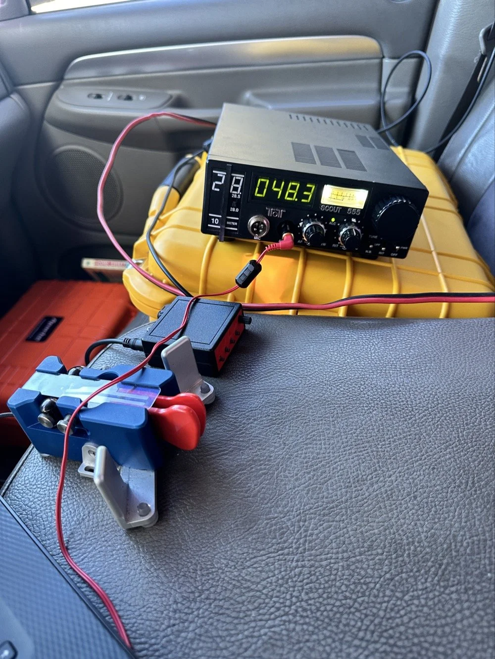
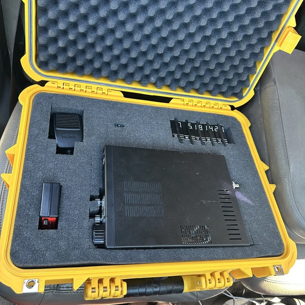
Side note, I also finally acquired a new case for my POTA Scout 555 radio. I still need to finish the pockets for the band modules when I get home, but I now have it in a proper case and not just sitting in a cardboard box in the back of the truck! Also, I made another 60 meter contact today… to the same exact person that I made the first one with a couple weeks back! HAHA! I think we are the only two people on 60 meters CW in the mornings ever…
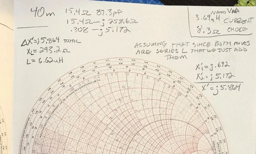
Here we see what I measured the other day while at a POTA park. What these numbers show is the antenna measurements for the band at the base of the antenna. I literally took the nanoVNA and adapted it to the antenna socket directly to eliminate the 50 ohm feedline from interacting with the measurement. As we will learn soon enough that you can use a piece of feedline (coax in particular) to move the base value around the smith chart should you need the starting point to be somewhere else. But I also learned something else about these starting point numbers below that I will share with you in a little bit.
At the top of the page, right next to the “40m” is what the nanoVNA reported that day at the park. (15.4 ohms and 87.3pf) you have to have two coordinates to plot anything on a chart so these are the two numbers you need to plot your starting point. Ignore the other notes as I am probably wrong on some of it and it actually makes more sense later. But the first thing I had to do was to turn these numbers into the proper numbers that the smith chart uses. This is called normalizing them. You see the chart is relative, you can assign whatever value you want to the center point on the chart and the rest of the chart is “relative” to this value. So if you were to work with 75 ohm coax and wanted to make an impedance matching network to work with it and having minimal losses, then you would assign 75 ohms to the center point. Since we use 50 ohms in almost all amateur radio (if not all) then our value is 50 ohms at the center point.
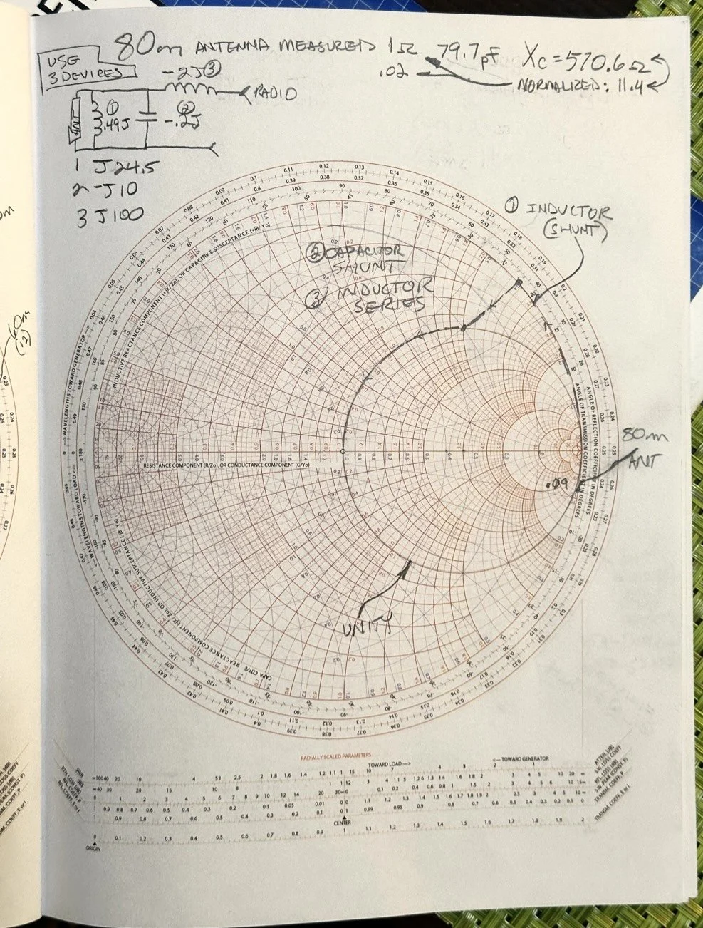
So here is my 80 meter plot (below) to get to a 50 ohm impedance from where it started at… yes… 1 ohm and 79.7pf capacitive! You see I am designing a matching network to couple my 50 ohm coax to a 18.4 feet tall telescoping vertical with a couple of radials thrown out on the ground. This is not even close to a matching antenna for the 80 meter band at all. Hence the terrible numbers to start with. Well, this was like those jokes you here from high school where you get something simple in the lecture in class about a subject then in the book it might show it with one more complication but the exam shows the Drake equation for the problem on the test! Well this is what happened to me as in the video above, the number in the video was closer to the middle of the lower half of the chart making for a more straight forward solution to the problem. I also did my admittance math wrong too if I am right…lol… since it is all inverted, but this doesn’t matter at this time. What you need to know at this point is that my problem lies outside the unity circle (that is the one I drew on the chart) and I need my “arc of movement” to cross this circle… it does but nearly at the infinity point (on the right side of the chart) which makes the math almost worthless… The reason the math gets pretty inaccurate is the numbers on the chart start getting logarithmic is value and so a small movement on the chart in this area makes huge changes in the values. You want your plot point anywhere else but here, yet this is where I am at in this blog post… haha
Knowing all this, I start this complicated, 3 position move to get me to the center of the chart. Mind you, I think this would actually work, but I am not sure if the math is mathing right at this time. (I am thinking the first move is a piece of transmission line to move the start point around the circle instead of an inductor and the second movement is also not a capacitor either so basically this whole thing is drawn wrong…lol) You will see why in a minute too as to why I dont know. The schematic for this movement is scrawled in the upper left hand corner of the notebook page if you wondered what it would look like to make this circuit. Two inductors and a capacitor to get to 50 ohms… how many antenna tuners have TWO inductors in them? I will help you out here… not many, if any. The number of inductors alone would make this a no go design for the most part unless is was going to be a one band wonder. Just remember I am pretty sure the math on this is wrong, the plot directions are correct, but I am thinking that the suseptance values are needing to be inverted to calculate the impedance for the two movements on the blue lines. Anyway, the point of this blog post is to show what is possible if you want to learn something new and it is not about the math around a smith chart…yet…lol I am diving back into the tutorials to figure out the blue part of the chart next.
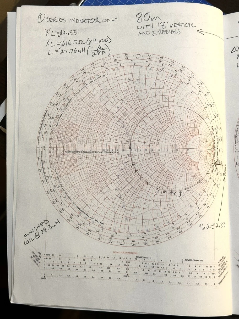
After I pulled my hair out for a while…wait, that don’t apply to me…I’m bald already… After getting over the frustration of trying to solve this problem, I redrew it on a fresh page and looked hard at it for a minute and had an epiphany… The plot point is not INSIDE the circle, or even anywhere closer to the middle of the chart at all, which would have been ideal, BUT it is really close to the unity line already. I mean REALLY close, so close in fact, I bet you could simply run around the unity line clockwise to the center point and just “eat” the misalignment on the horizontal resistance line of such a tiny amount and no one would even notice in the real world. You know what this matching network now looks like? A huge by large inductor is what, just a plain ole gigantic coil… Moving clockwise around the impedance lines (the red ones) indicates adding inductance to solve the problem. This is what all the antenna companies use when you buy a mobile 80 meter whip antenna if you think about it, just a huge load coil and nothing more. If you were to zoom in on this, I am guessing the resistive value when you get to the end of the arc, at the horizontal center line (which is the pure resistance line) would be something like 49.2 ohms or something close to that, literally less than 1.1 : 1 SWR maybe less to be honest.
Armed with this knowledge, I wanted to test this theory. So I now needed a way to make a coil to insert between the feedline and the base of the vertical to see if I had learned anything. Well I had this new scope / meter / signal generator widget and I had a way to make a capacitor, I then remembered a video where I guy showed how to measure inductors and capacitors with only a oscilloscope if you have one known device. Well, I have a capacitor that I made and I can measure it with the new meter, so that will give me the “known”.
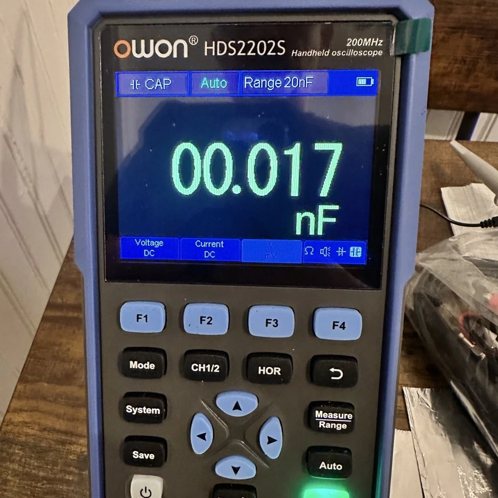
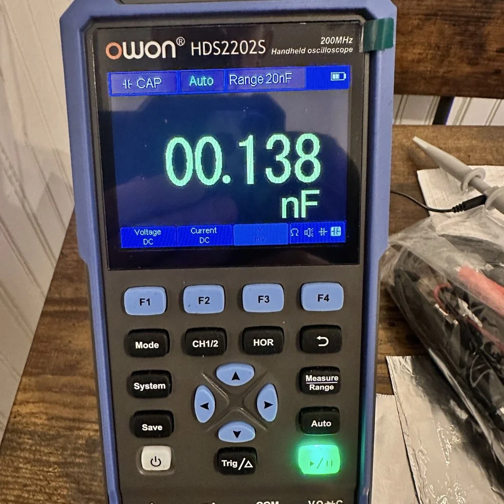
So I fire up the new meter and plug in the leads and find this. There is no way to “tare” out this number either so you simply have to subtract it from what ever you measure. I figured this would be pretty easy so I just went with it. Below is a photo while I was trimming the capacitor to a size I wanted. I was looking for 100pf and as you can see below on the meter, I was getting close. This is measuring right at 121pf in the photo. I would trim off the edge of the sheet and then check it again, rinse and repeat till it was close to what I wanted.
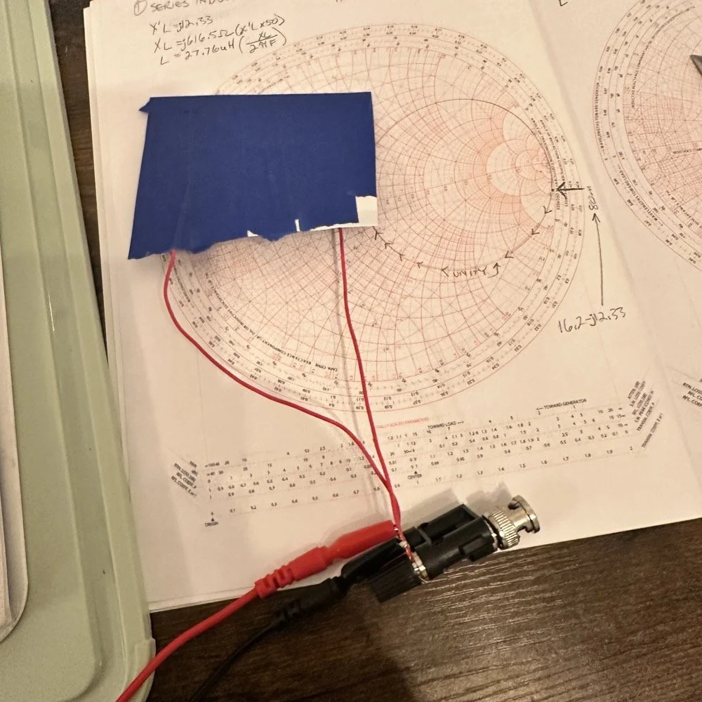
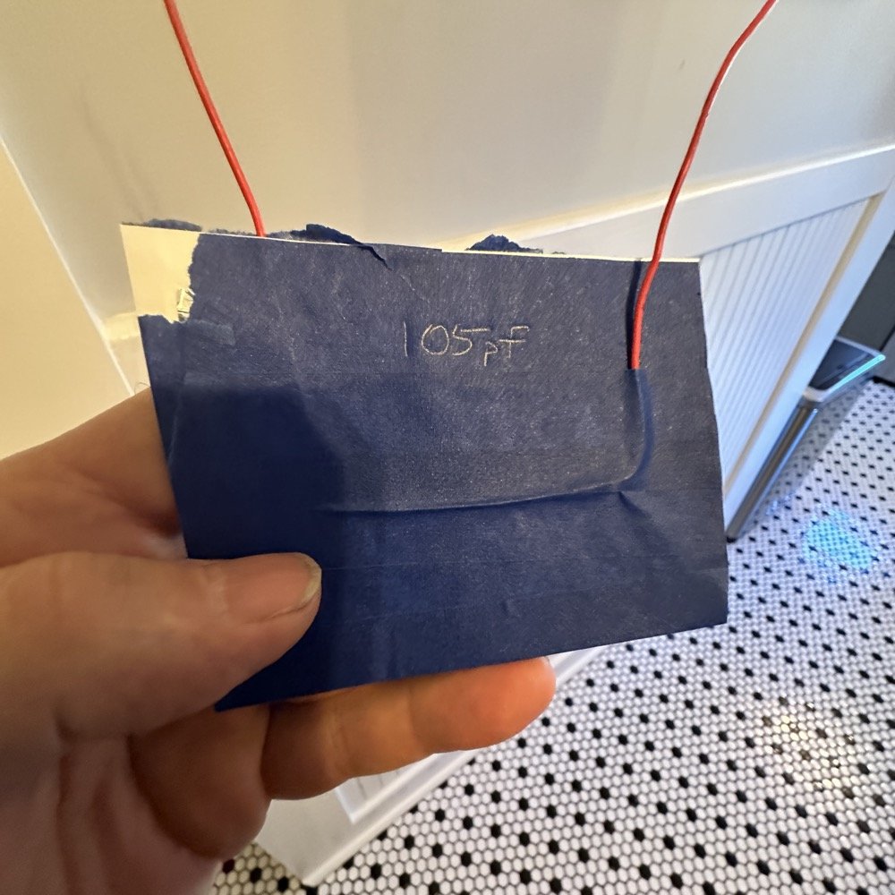
Once I had my brand spanking new capacitor made and trimmed to size (105pf), I setup a test fixture to do my test with. The test fixture is also expedient since it is all that I had was one of those “BNC to binding post” adapters and just used it as a sort of bread board to attach all the parts to the system. It worked, it was pretty janky, but it worked. All that we have here in reality is a parallel tank circuit. It will resonate at one frequency natively and I can measure that and then use a simple online calculator to see what the inductance is based on my capacitor value and the frequency of the tank circuit. How do I get it to resonate then? Simple, use a battery…
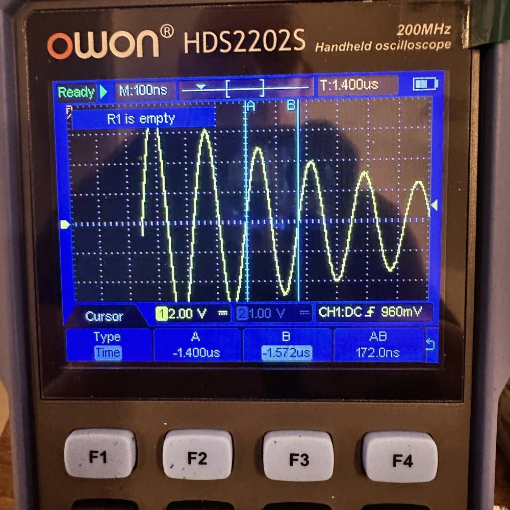
In the other video I had recently watched he showed simply setting the scope to trigger off of a voltage level close to the value of the battery which will allow the scope to capture the ringing of the tank circuit if you pulse it with a battery. I just took a AA out of my pocket flashlight and used it, set the trigger to normal and set the trigger level to about 1 volt and started touching the battery to the two red wires going out to the left in this photo below. This biased the tank circuit (simply applying a dc voltage across the capacitor and charging it) and I was rewarded with what you see below on the scope in the below photo. To be perfectly honest with you, I had done so much wrong in this process that I was honestly surprised that it worked. I even had to show it to Teresa and she had literally zero idea about what she was seeing here, but I had to show SOMEONE that it has actually worked!
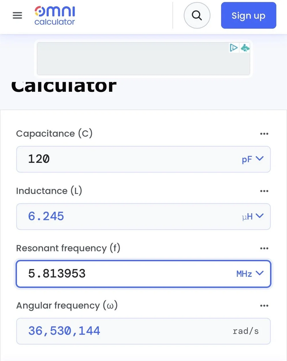
The ringing the scope captured is nice and clean and I was able to measure the period of the sine wave at 172 nanoseconds. Transforming the time into a frequency is easy, you simply invert the number or divide 1 by .000000172 and you get 5,813,953 hz. This frequency is not relevant to the ham bands but is only useful in telling us what the value of the inductor is, which is what we want anyway. As you can see from the screen shot below, this inductor is 6.245 uH (micro henrys). I did the plot on the smith chart for 40 meters for this antenna and came up with almost exactly this number, I came up with 6.62uH on the math. This also makes sense as I did this physical coil for the 213” (17.75’) WRC vertical and not this one that is longer that I am using now 221” (18.4’). Another possible reason for the variation from the measured and the plotted values is that my capacitor value could be slightly different from being moved around or being in proximity to metal or some such. You could touch the capacitor with your finger tip and the value would change so this is probably part of the variation…
I made this actual load coil by guessing to be honest, I did use the nanoVNA as a SWR meter when I made it and I would take off a coil or two and measure it and I simply walked the null in on the antenna for 40 meters that day. Now I know how to use a smith chart to do that math ahead of time. That is pretty cool.
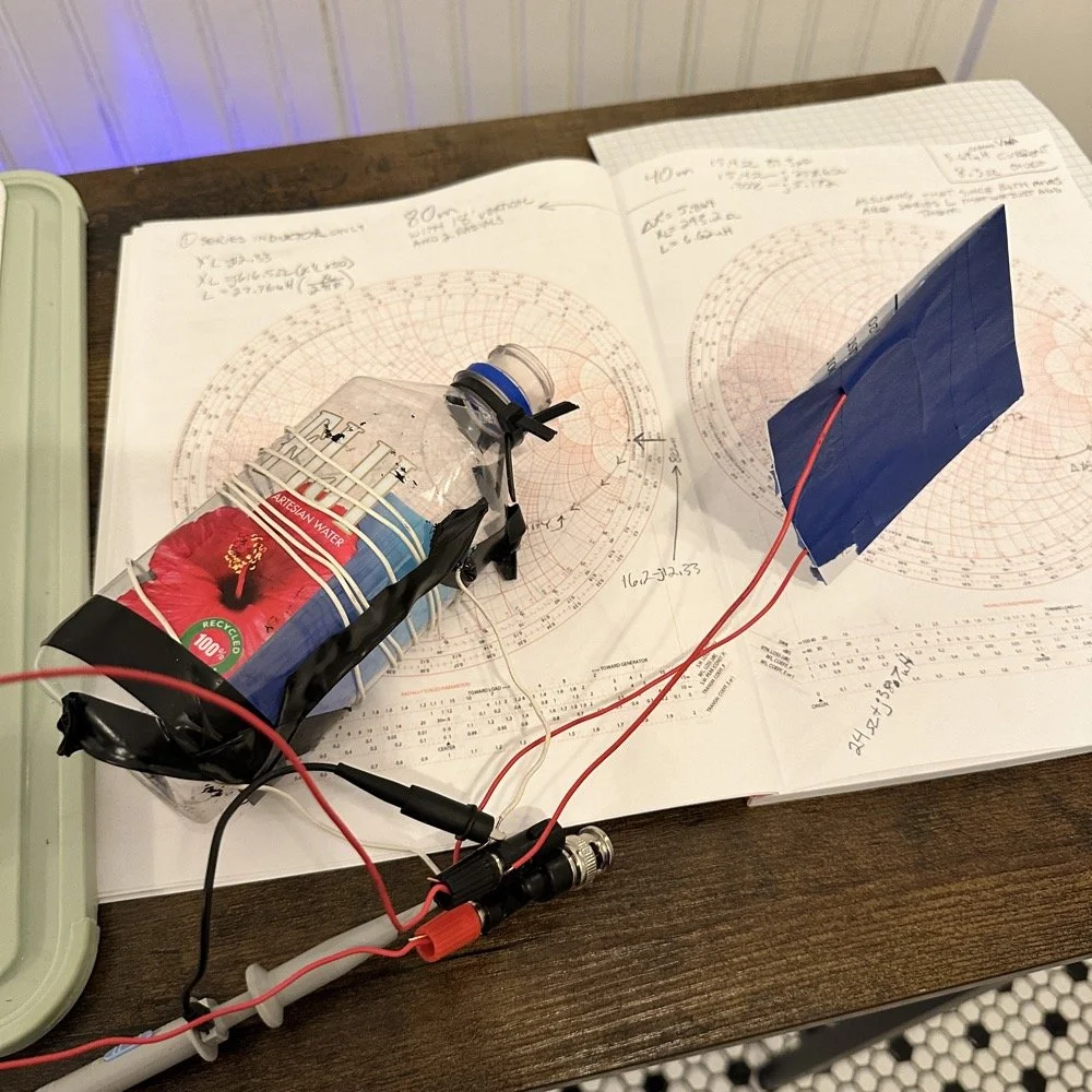
Literally using trash to resonate as a tank circuit is kinda cool to be honest with you. The wires for the capacitor are simply taped to the aluminum foil, nothing more as I didn’t have a way to solder them together or anything like that. This was truly a temporary test fixture for experimentation.
The next logical step was to make an inductor for 60 meters and to hook it up to the antenna and measure it with the nanoVNA to see how close I could get it. This is where things started to go south…
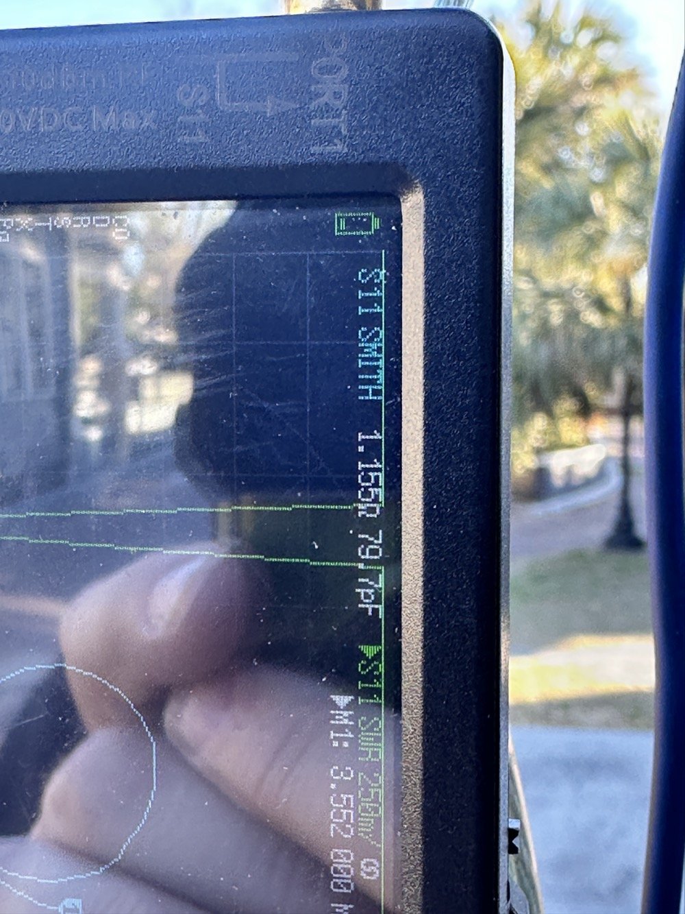
First of all, I had problems replicating the same resistance and capacitance from that day at the POTA park. The photo of the VNA above shows what I am talking about. Now it is 1 ohm… yeah basically a dead short for the RF. But more importantly it is different from the day of my test which was about 10 ohms (if memory serves me) but basically this doesn’t matter when you get to the region of the smith chart that this plot is landing in. The capacitance is what really drives this position between these two numbers and it was virtually the same. The amount of inductance will be more for 1 ohm but not a whole lot more.
Well what happened when I hooked up the coil and the vertical and stuff in the driveway was a whole bunch of nothing! It just made a circle around the outside of the smith chart, which is bad if you don’t know. You want your line to go through the center of the chart at the frequency you want to use and if it goes around the outside it ain’t going through the middle!
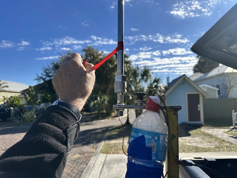
Deflated that I had probably done all that math wrong…again… I was about to throw in the towel when the wind blew and the plot on the nanoVNA moved towards the center! What just happened??? I start messing with this and that, as you can see in the photo above that the coil output wire is just poked into the coax port on the antenna. This has to be the worst way to make this connection, but if this is all you have, then this is what you do…
I could grab the vertical and that would make drastic changes to the smith plot, so I thought about moving the antenna without touching it and I found a roll of electrical tape and used that to tug on the vertical as it is in a QD mount (which is not a great connection to be honest that I have found). I even cleaned some stuff to no avail, but when I put the tape on the antenna and pulled it in certain directions, I would get the plot you see below. Notice the marker is at 5.340 mhz and at 55.2 ohms and just 1.49nf capacitive. This is less than 1.2 : 1 SWR and I am sure that it is off a little because of the system losses at this point. All the loose and dirty connections along with the random radial placement (I find this makes a pretty large difference with my systems) made getting repeatable results almost impossible. This told me that the coil worked though and that my math was not wrong! I had actually learned something here!
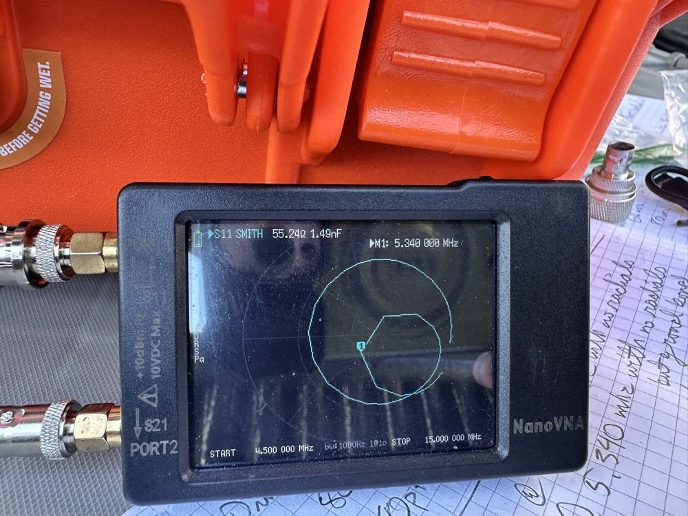
Once I figured this out and took a couple of photos for the blog, I tore the system back down and put it all away so I could get started on this write up about it. This has been an amazing process to do this and I learned way more than just how to do impedance matching with a smith chart. I learned that my system is way too inconsistent to simply make a coil and expect it to work in the system. If I had all the parts hard mounted in place with corrosion inhibiting paste on the connections then I could calculate this coil and it would drop right in. I was blown away by this and cant wait to find another use for my smith chart notebook. I hope this has helped you in some way either by simple entertainment or by learning something about smith charts and antennas, or maybe that there are YouTube videos about how to do this sort of stuff, either way, thank you for reading to here and I hope you come back for more of my ramblings in the future!
You can help support this website by using these Amazon Affiliate Links:
QRP/Portable Radios:
Antennas & Tuning:
CW Equipment:
Power & Accessories:
Organization & Transport:
BONUS ITEMS
73
WK4DS - David