Today I was back over at my local park and while setting up the activation, I took note of the Smith Chart values for my tuned antenna on 20 meters. This took me down a rabbit hole and now I want to implement the changes to see how well it works.
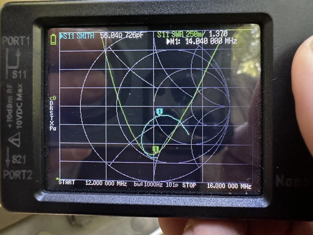
As you can see in the photo, I had the SWR plot on at the same time as the Smith Chart. When I am “on a clock” I will ignore the Smith Chart portion and just focus on the SWR plot. This is simple as all I have to do is place the radials in the usual position and then collapse or extend the antenna a little at a time to move the null over to where I want to operate. Is this antenna efficient? Not really. Does it get me on the air quickly and making contacts? Absolutely!
The information on the display above shows a lot of information. You can see with the SWR plot that the antenna is still just a touch too long. It is close enough to use, but if I wanted better bandwidth for CW use, I should shorten it a little more. You can also see where the same value is on the Smith chart at the same time. It is plotted below the resistive line, so it is capacitive. This is also confirmed at the top where you see 726pF. It is also above 50 ohms of impedance since it is inside the unity circle for 50 ohms, just a little bit.
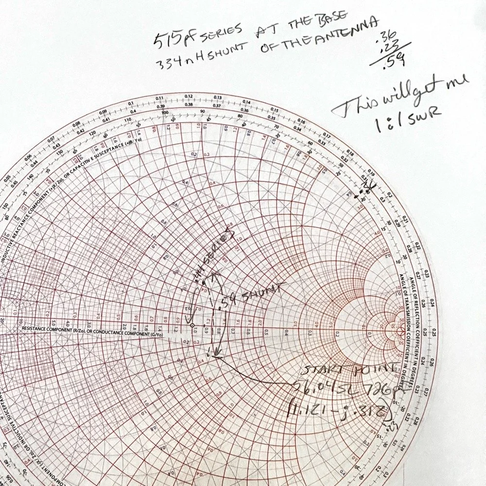
The Smith chart is really cool once you start understanding it a little. BTW…a little is all I really know about these powerful tools. It would seem to be counter productive to put an inductor from the antenna radiator to ground. It would also seem even more so with one of a very small inductance. But the Smith chart don’t lie… It looks like a hand wound air core inductor and a 550pF trimmer cap are the goodies here. or at least a 500pF cap and a 50pF trimmer to tune it with. The catch here is that the inductor shunts to ground BEFORE the capacitor is wired in series with the antenna. This is because my first “movement” on the chart is up (which indicates using inductance) and along the conductance lines (blue lines). THEN the capacitor is in series with the antenna after the inductor.
This means I have to make a little board up that will allow me to plug the coax into one side and connect it to the base of the antenna on the other. Since I use BNC connectors in the field, this should be pretty easy. I don’t want to let the cat out of the bag just yet, but what this really is, is a L network antenna tuner…
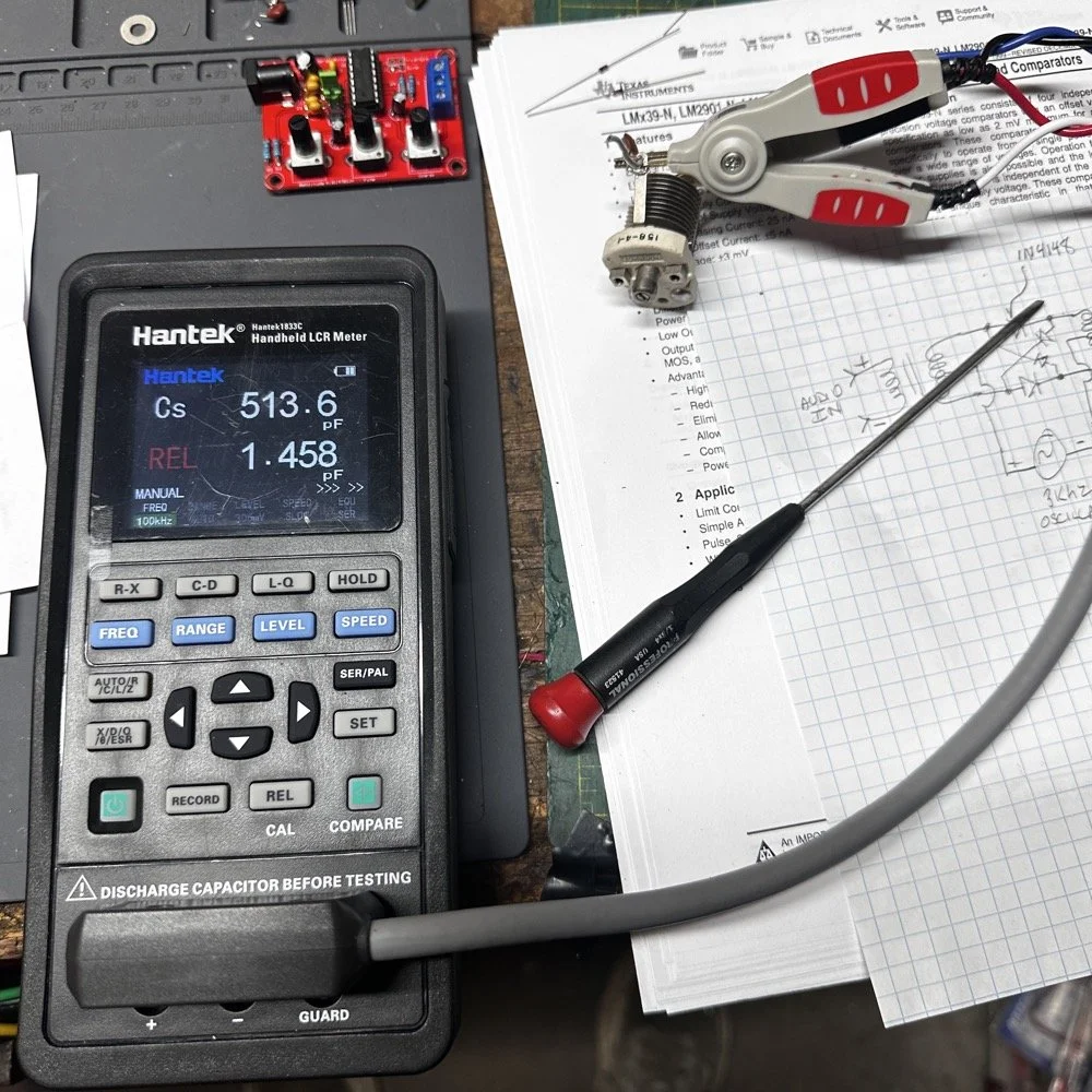
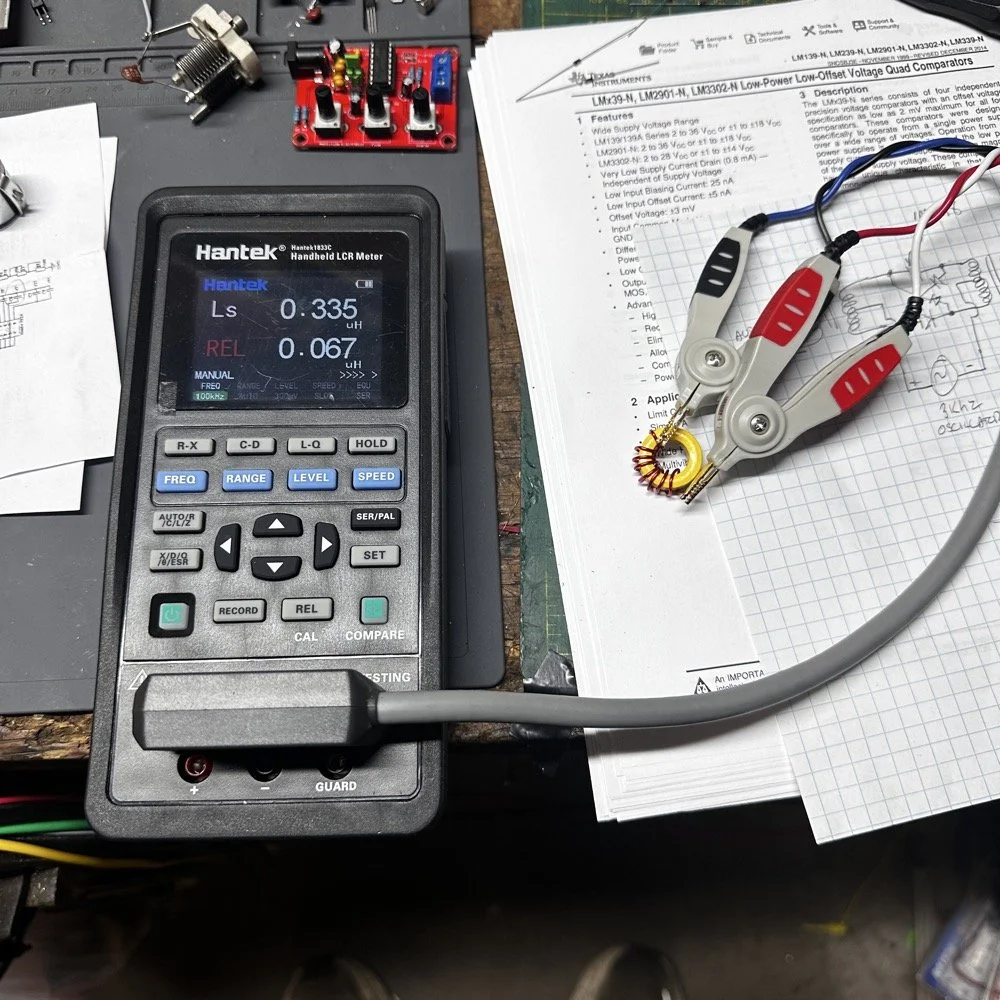
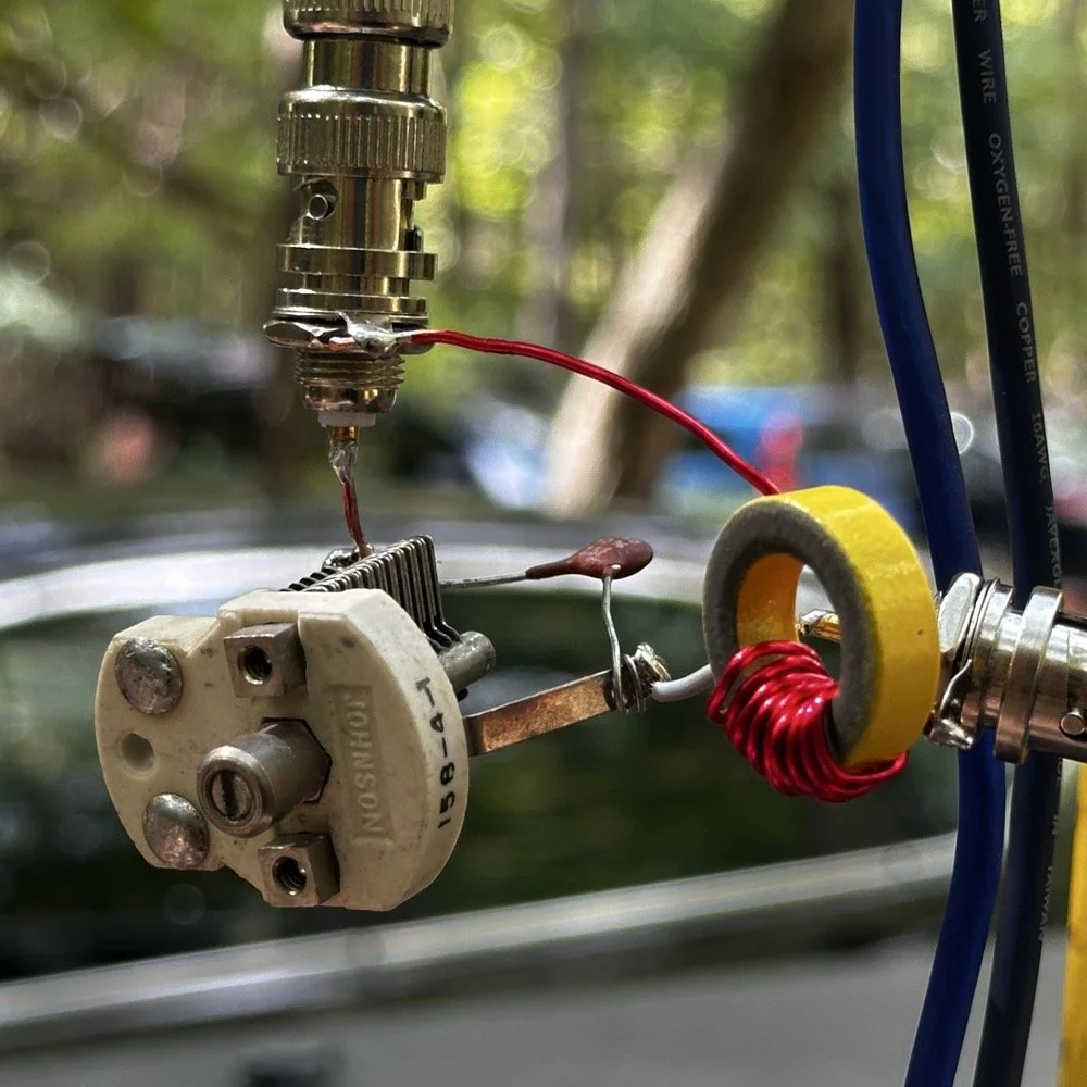
To get the capacitance, I soldered a 560pF capacitor across the 10-70pF trimmer capacitor. The 560pF actually measures 490pF so this with the trimmer gives me a decent working range. I used my Hantek LCR meter to measure the inductor and capacitor before I built it out. The REL in red letters means I “zeroed out” the display prior to testing the parts to remove the inductance and capacitance from the meter leads. I tried a few iterations of the same piece of magnet with to get it to 330nH and it required a toroid to get it to that level of inductance. Without the toroid, I was only able to get about 95nH max out of it. It is also a lot more stable with the toroid core too. So there is that. I am pretty sure this core is not really rated for 50 watts, but we will see. I figure I will call QRL and then “test” on my call for a minute, on a higher band where it is usually a ghost town, and then go out and see if the core is hot. I hope it can handle all the stress I am about to put to it…haha,
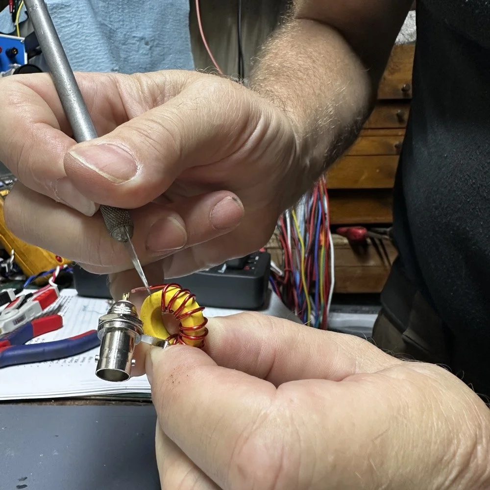
This has been the easiest way for me to get the enamel insulation off of magnet wire. I simply scrape it off with an Exact-o knife. I tried burning it off but it makes a mess. I also tried sanding it off and this does work really well, but it is hard to do and slow. So I scrape them. I dead bug style built this one as it is simply me playing with the idea and wanting to see if my math actually works like it is supposed to. I am fairly certain that it will work, I just want to see if I can get it to do it in the real world too. The SWR was completely usable the other day and whatever it was, so don’t think this is needed for the setup I was using. We are learning here.
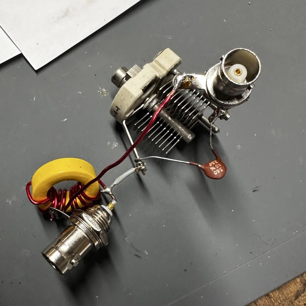
Here it is. I simply used another piece of magnet wire to connect the grounds from one socket to the other and then simply soldered the rest in place. This will have all sorts of stray capacitance issues but as long as I get it to sit still, I should be able to tune it to the setup for the next outing. It will vary a little from one day to the next so this is why I used a trimmer. Also the toroid is adjustable somewhat too. By spreading out the turns on the core, I can lower the inductance some, so this should work pretty well. The cap is technically out of tolerance (and this is probably why I was able to get them on eBay so cheap too) but the measured value was just what I needed for this project.
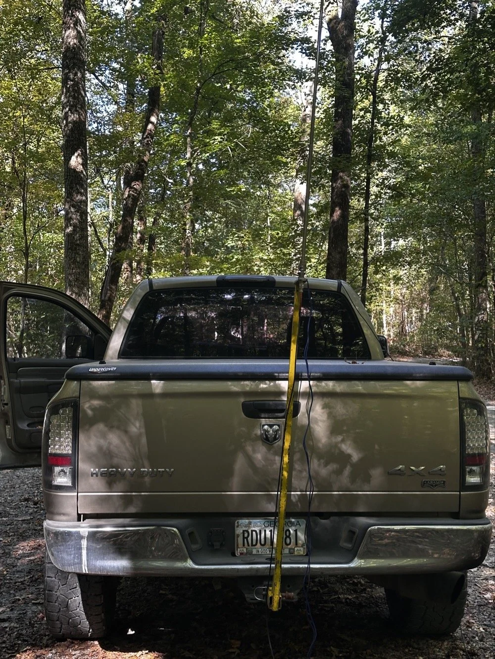
So the antenna on the first trip out for this test, was leaning over to the right. This was so it would not touch some tree leaves near the top of the antenna. This problem will be going away soon as we are entering fall… So this is the setup I need to replicate when I perform my test. Lucky for me, I took a photo of the nanoVNA before I took it apart so I can see when I get it close.
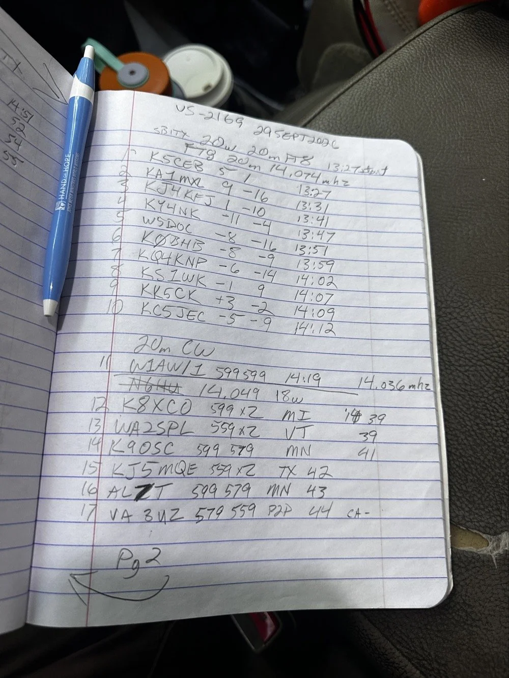
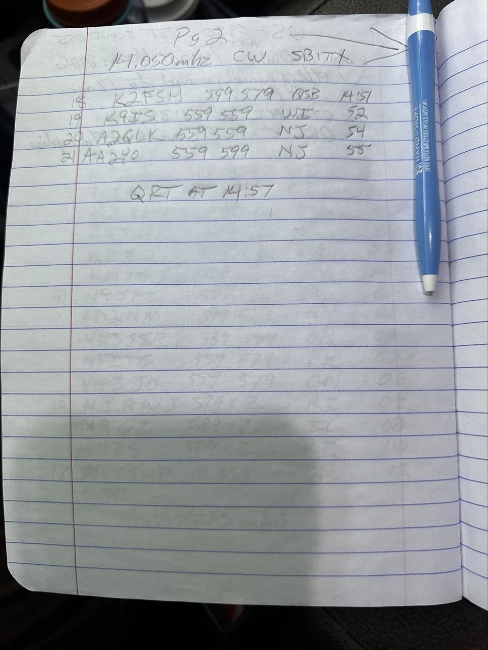
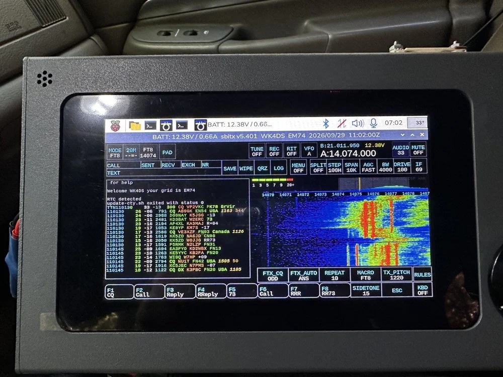
So today I wanted to use the sBitx and see how many FT8 contacts I could get before I switched over to CW. The mini-goal was to secure the activation with just FT8 today then do what ever. Well, as you can see, that was a win. Then I wandered around the band a little and found W1AW and got them in the log next. QSB got to N6HU before I could work them… After that I was able to work several more before I ran out of time. It was a great day at the park! Come back next week to see what happened with the antenna tuner I built!
This latest version of the sBitx OS is really good. This radio was really economical when you consider what your getting. It is only 40 watt, (mine is the early version with the 40 watt amplifier and not the 25 watt version that ships now). It does have a pretty inefficient amplifier design as it loses output power the higher you go in the ham bands. But you know what? It will operate FT8 and FT4 natively INSIDE the radio with no other gear needed. That in itself is amazing!
Today is the day of the big test to see if my math works. I took this amalgamation to the park with me so I could replicate the setup and get it back to as close to what I had as possible the other day. I even parked in the same place. I simply used a BNC to BNC adapter to couple the two bulk head connectors together. This allowed me to connect the matching network to the base of the antenna. You can see both the capacitors and the inductor in this photo and now I have them wired. This should be close to 50 ohms impedance and will probably need a little adjusting on the trimmer cap and maybe moving the coils of wire on the toroid. Other than that, it should be good to go.
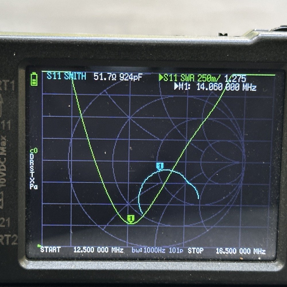
These two photos show what the system looked like before I added the matching network I had made and the lower image is after. As you can see above, the SWR plot looked really good with the impedance being really good. It was close to the other day as well so I should be able to adjust the L network to clean this up some more too.
What you see below is the result after I added the L network to the system. The plot is now over 2 : 1 and the impedance is inductive finally. I have had these be capacitive in nature for a very long time and it was good to see I had moved it to the inductive side of the graph. This tells me that I am on the right track. You can also see that it lowered the resonant frequency of the circuit too. Now what could have caused this? I was needing it to move the graph to the center of the chart and we ended up with this mess instead.
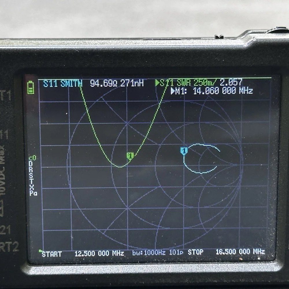
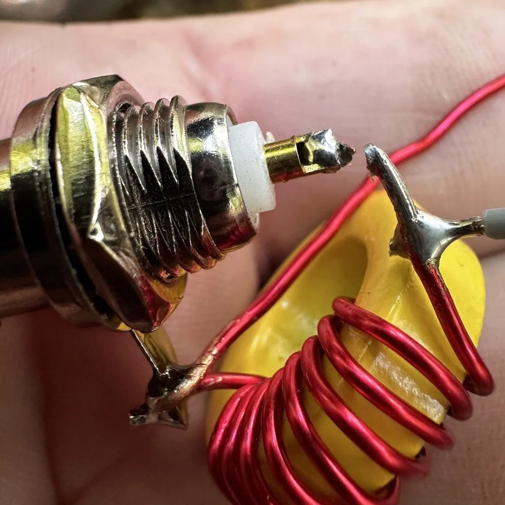
So now it is back to the drawing board to figure out what I did wrong. I am not sure what has happened here. Maybe I measured my components wrong. Maybe I wasn’t setting up the nano VNA correctly. Maybe I did the calculations on the Smith chart wrong… All I know is that it did not work like it was supposed to.
I am going to re-solder the broken solder joint you see in the photo above, then re-test the circuit. Maybe it was a bad solder connection that was causing the error. I really don’t think it is though…
Sometimes you win sometimes you lose sometimes you make a mistake, this seems to be one of those times…
You can help support this channel by using these Amazon Affiliate Links as well:
QRP/Portable Radios:
Antennas & Tuning:
CW Equipment:
Power & Accessories:
Organization & Transport:
BONUS ITEMS (Optional 16-20):
73
WK4DS-David