When I tell you that I have been working on this one for a while, I mean it. This project has been going on for several months. I drew countless pages in my pocket notebook about how to solve this problem. It just would not work. You see, it is more complicated than you think it is. It is also as simple as you think it is too…
The Problem with LiFePO4 batteries and Solar Charge Controllers
Here is the plan, I need to add a small circuit that will watch the battery level and determine whether or not to enable the switch to run solar power directly to the house during the day. This needs to be automatic and needs to be adjustable so I can fine tune it once installed to match the battery system I am using.
The problem is this, if I leave the current system in play all the time, the new lithium iron phosphate batteries will shut down and go to almost zero volts in protection mode. This is the internal battery management system protecting the cells. This only happens when I have several overcast days in a row. You see, the solar “daytime” detector will still enable the solar to the house as long as the AC inverters will power on. The problem is that now the voltage on the battery terminals is almost zero if that happens. The solar panel charge controller wont “cut in” and deliver current to the batteries until it sees a battery connected. The batteries cant charge because the charge controller wont turn on to charge them. SO I have to “jump” the system off with another battery from the other bank. I literally have to take another battery loose from the other set and slide it over to this set and touch the cables to the dead cells to start the system. Once the charge controller sees the voltage, it comes online and the system will start to recover.
This wasn’t a problem with the old lead acid wet cells as they would still have voltage in them when they would get too low to power the inverters. So the next day they would start charging. Not so with the LiFePO4 batteries. They will leave you high and dry with this type of system.
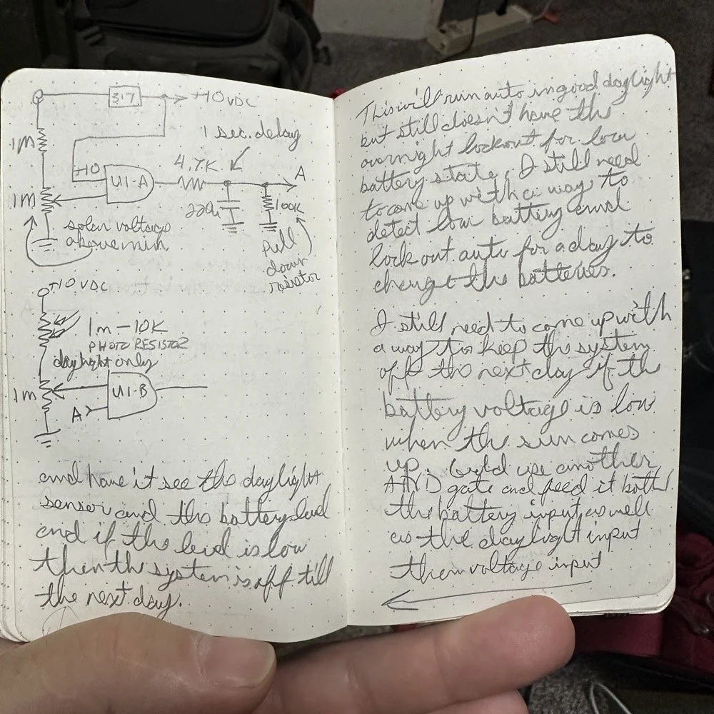
How to come up with ideas to solve your electronics project problems
I probably have 20 pages in my notebook that look like these. Sometimes it is good to simply write down your ideas. Even if those ideas turn out to not be right, you should still write them down so you can analyze them to learn from them. This is some of that writing. Also I was writing in a secret Gen X code…haha. I would think of an idea and just get out the notebook and draw a simple circuit and write down what I was thinking. This way I could go back to it later and not forget what I had thought of already. Another thing that helps is to read back over your notes occasionally so you don’t reinvent the same idea more than once. Yet another reason is that after the idea has soaked a few days (or even weeks) when you see it later, the solution might just jump off the page. Sometimes it just takes a while to get the whole concept put together.
I really wanted to use photo sensing elements in the design (as you see in the drawing above) and I finally did… The thing is that I didn’t need to add any, the photo sensor is already in place… I ended up using the daylight solar detection cell…The same solar panel that powers up the relay that switches on the inverters and then turns on the relays for the house to run on solar during the day automatically. This circuit I built will only need a few milli-amps of current to pull in the little solder on board relay that I used. It will only need this current it the batteries are also under the voltage threshold and that is above the cut off level. The nice thing is that as you see below, I was thinking I needed a timer to carry the whole day when I figured out that if I use the solar panel like I am using it, then the sunlight will keep it turned off anyway…even if it charges above that level during the day.. It will simply engage the SCR which will stay on till the solar panel shuts it off at the end of the day and then the system will automatically stay off through the night till the next morning when the system has been reset and it starts all over again.

The circuit concepts for a LiFePO4 Solar Battery Monitor
I started out trying to use NAND gates as I had some of those left over from the other battery monitor project. This turns out to be doable. The problem is that it starts to rapidly get overly complicated and you have to work in voltages that are where the gate operates at. This is where things got tough for the NAND gate. The gate has a threshold where it trips from one state to the other and you have to tune the circuit to work in the region. It is really consistent fortunately. This makes them work for this. I did some online searching and found that Texas Instruments also makes the LM339N comparator chip. This literally takes an analog signal (a voltage level) and compared it to another analog signal (another voltage) and if A is higher than B it flips states, and if B is higher than A then it flips the other way. This is literally the answer to my problems!
The thing that makes it special is that you don’t have to tune the circuit to the trip point of the comparator but rather you choose the level it trips at and compare to that. Brilliant and so much simpler!
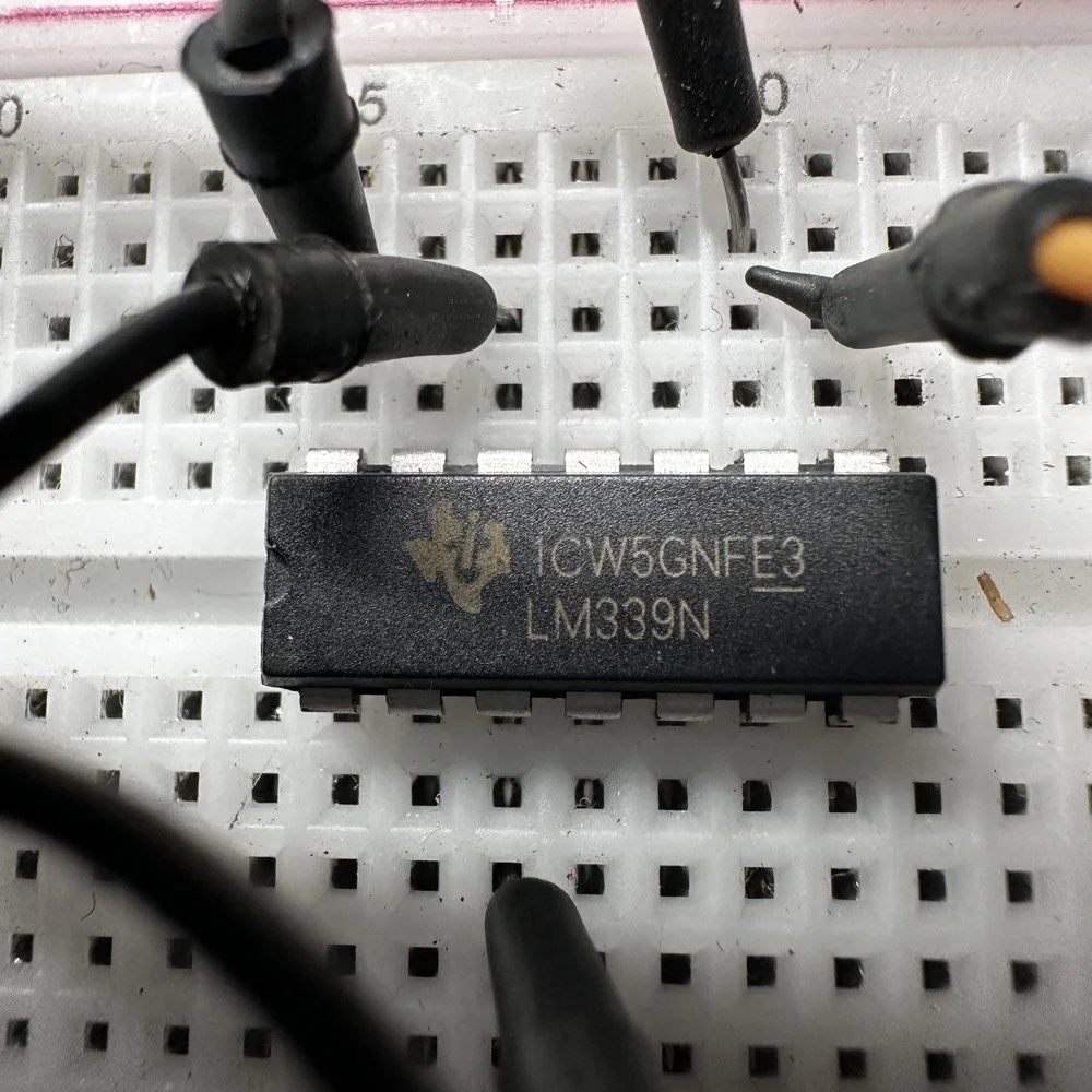
I promptly ordered some chips and went to work playing with them. The chips I prefer are what is known as through hole style DIP packages. I still build on perf-boards and have not gotten to where I can really work with surface mount stuff yet so I still use the old through hole parts for my builds. This is supposed to be a genuine Texas Instruments part, but these days, you really don’t know unless you buy from Mouser or Digi-key… These came from Amazon, so who knows…haha. I do know that they work as advertised for the application that I wanted them for, so it is all good right now.
I had to come up with a way to detect the voltage and then also compare that voltage in the same circuit against two inputs. After a little thinking, I came away with a regulated power supply adjusted down to some level below the supply and then the other input is run through a simple resistive voltage divider. The LM317, while antiquated, still works fine. It doesn’t hurt that I have a drawer full of them too. I am moving to the newer and better LM350T, but for this one, it is the good ole 317. So what I did was this. I used my adjustable power supply to set the “supply” to my desired cutoff voltage of just over 24 volts. Then I simply turned up the adjustment on the 317 till the state flipped on the LM339. This had to be the easiest calibration sequence in the history of the world… haha. I bought quad packages because they were in stock. The smarter play would have been to get the dual packages instead, but you use what you can get and I didn’t want to wait.
Below shows how they are connected internally and it really is that simple.
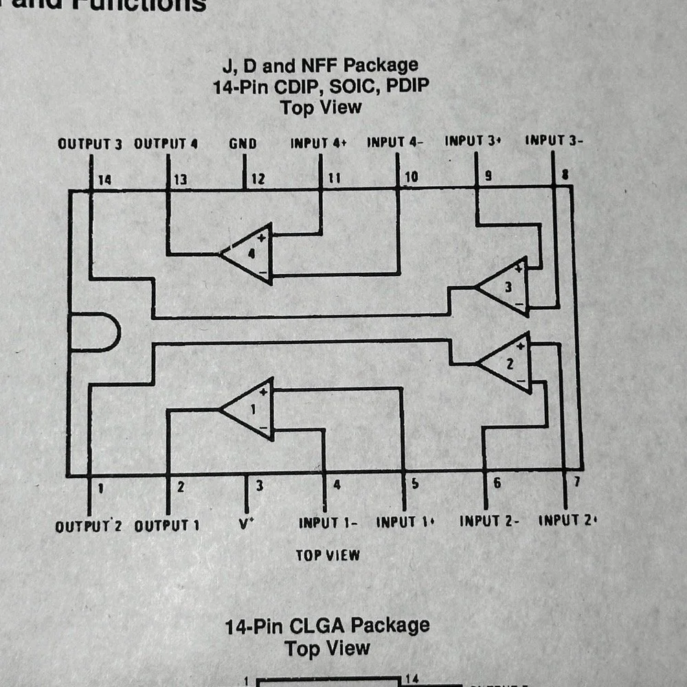
The LM339N works by comparing two analog signals in what they call the ( input - ) and the ( input +). These do not have to be positive and negative, but rather they are simply two levels that are compared. It isn’t as complicated as I was trying to make it at all. The first thing I did was put a circuit together on the bread board and play with how it works to see if I could get it to do what I wanted it to do. Turns out it would work just fine after I figured out a few things like the fact that the SCR needs to be on the ground side of a relay if you are using it to latch a relay in the “on” state. If you put it on the power side, it acts like a switch and turns the relay on and off as the voltage moves above and below the threshold. Hold that thought…
I did some simple ohms law math for the current draw needed to pull the SCR gate in and to fire the opto isolator, so these devices would work and that is what those 1330 ohm resistors are about on the bread board. By the time I had taken this photo though, some of the parts had already been pulled to move them to the more permanent solution… perf board.
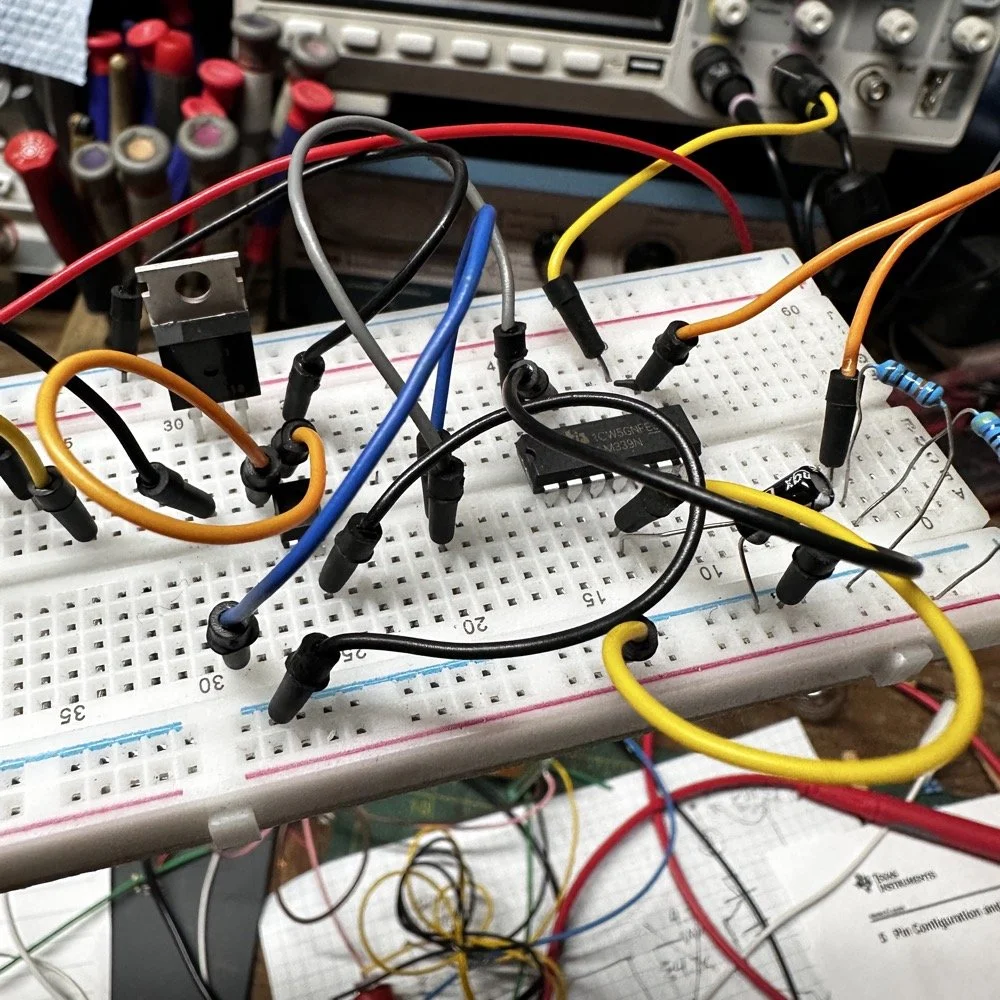
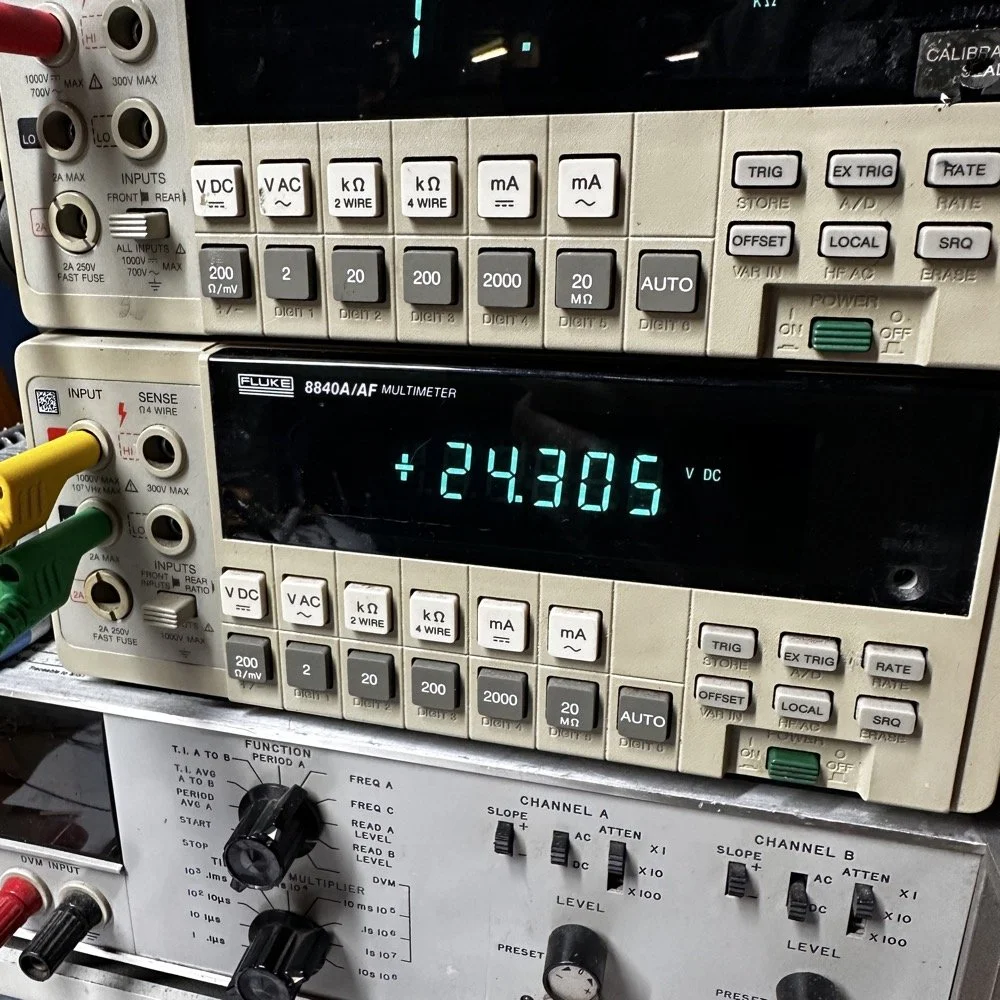
I set the trip point for now to 24.305vdc and will see if that will work when I get it installed on the system. You can see that I love these old Fluke 8840 meters as I now have two of them. One is this A/AF (Army/Air Force) variant and the other is the standard commercial variant. They are both incredible bench meters as well as a few others that I have on the bench. I wanted an Agilent or Keithley meter, but they are WAY more costly and I dont do work that is that important at this time… haha.
Building the LiFePO4 Solar Battery Monitor Circuit
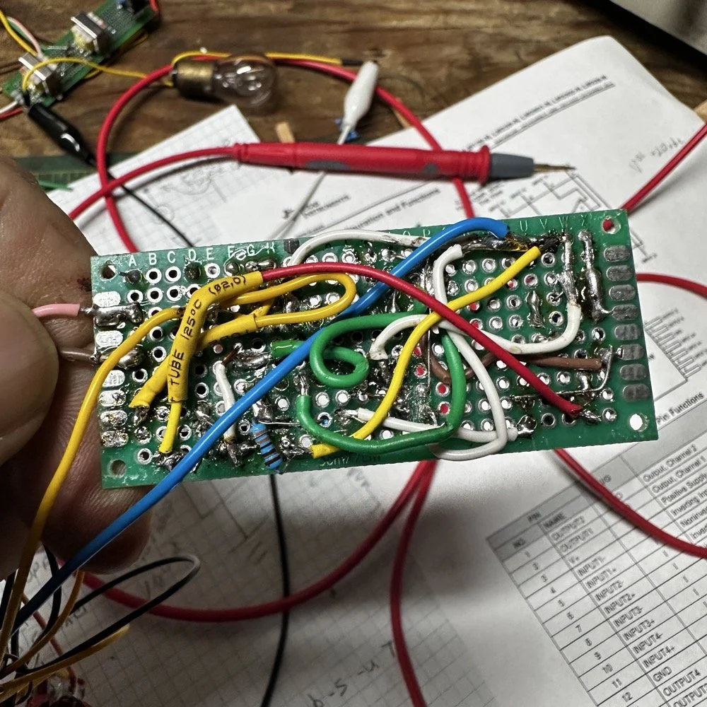
Below you can see that the perf board design is truly just “come as you are” construction. You just place parts where they will fit and wire them accordingly.
I seem to always run into problems with this though as the pin outs are reversed when the board is flipped… remember what I was saying earlier about wiring the SCR backwards? Yep, I did that while LOOKING AT THE DRAWING I MADE SO I WOULDN’T DO IT!!! That is how easy it is the get things mixed up when building these kinds of circuits and remember, mine was simple!

The top of the board looks great…it is when you turn it over that you see the real mad scientist. The bottom looks like something out of a horror movie! I tried to keep all the components on one side and the wire on the other, but it was just going to be too much work to remove the other resistor and put this one in its place. Haha. So I simply soldered it in parallel with the other one. The other resistor was a really high value so it changed the circuit very little anyway. So I have one part on the back… such is life.
What amazes me is that this circuit started up and worked perfectly (once I moved the SCR to the correct side of the relay). Seriously, that mess actually worked like it is supposed to somehow.
Now, this is not the first iteration of this board. That is partly why the wiring looks as rough as it does. I did attempt to use a transistor to start with as a buffer between the comparator and the SCR but it would not work reliably. Enter the opto isolator. This little gem solves that problem in style. I have grown to love these for buffers between two circuits. Simple to use and reliable.
Using the opto isolator keeps the two voltages separated so that there is no cross contamination.
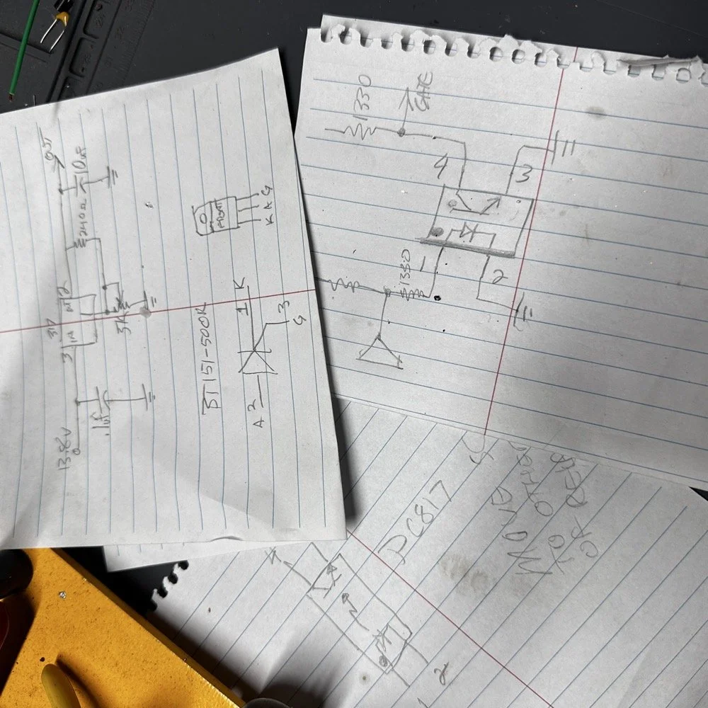
You can see here that page on the upper right is the drawing I finally settled on. This one is the one that worked by pulling the gate to ground when the comparator output is high.
There is no need for an on delay timer since it is constantly looking at the battery level and generating an output relative to that level. When the sun comes up, it will power up the SCR side of the circuit and set the relay based on what the opto isolator is doing when it comes on.
Comparator output is high? Then the SCR gate is pulled to ground via the output from the opto isolator and the SCR stays off. Comparator output flips low, then the opto isolator shuts down and the gate of the scr gets sufficient voltage and current to fire and latch.
Finally, testing the comparator circuit in the actual system!
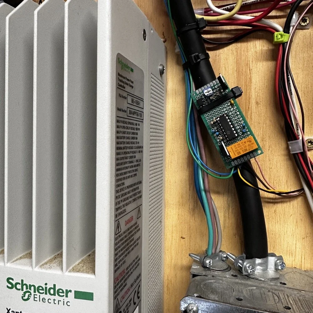
Here is my “temporarily” permanent installation in the solar power room. I will run it a while and if it works like I want, I will move it into a project box. Initial trials so far look promising. This just might be the answer I was looking for.
Do you experiment with little circuits to solve simple little problems around your house?
Support this website by using these affiliate links to shop on Amazon:
My Soldering Station: https://link.amazon/B01N4zQYx
Solder: https://link.amazon/B003Fyezg
Solder Wick: https://link.amazon/B0cSEsTQN
Hook Up Wire: https://link.amazon/B0i7fzwLM
Long Reach Needle Nose Pliers: https://link.amazon/B01Cifgx5
Perf Board: https://link.amazon/B0fpuDPOt
TI LM339N Ships: https://link.amazon/B00gFZr2q
OWON 3 in 1 Meter:https://link.amazon/B0gGsVWeH
Thanks and I hope to hear your stories soon!
David